
Instruction Manual


8
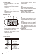
[Unit Display Section]
21
19
16 17 18
20
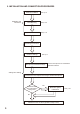
12. Network reset key
For more information, see p. 27, “Network
Function.”
Holding down this key places the receiver in
maintenance mode.
Pressing this key again sets the receiver back to
normal mode.
13. Remote indicator [REMOTE]
Lights when the receiver is in remote operation
mode.
Flashes when a PC uses the Receiver location
conrmationfunction.
For more information, see p. 27, “Remote/
Local Mode Setting.”
14. Network status indicator [FULL/COL]
Lights when network is in full duplex communication
mode.
Flashes when data collision is detected.
Remains unlit in other conditions than specied
above.
15. Network status indicator [LINK/ACT]
sLit when a network is connected.
Flashes during data transmission or reception.
16. Received signal strength meter
BargraphLEDslighttoindicatestrengthofsignal
received by the corresponding antenna.
17. Audio output level meter
Bargraph LEDs light in response to received
audio signal output levels.
18. Receiving antenna indicator
LED corresponding to selected antenna lights.
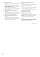
19. Batte ry indicator
Display Hours remaining
4−5.5hours
2.5−4hours
1−2.5hours
0.25−1 hour
(Batteriesneedtobe
replaced)
Flashing
0−0.25 hour
(Batterylifeisabouttoend.)
Indicates approximate remaining transmitter
battery life (alkaline batteries).
20. Channel indicator
Displays the received channel number.
Tip
Dots located at the lower right of both the Group
andChannelindicatorsashatthetimeofIDOFF
setting.
The “CH.S.” indication is displayed while scanning
channels.
Other indications may appear or entire indication
may ash when the unit’s function is remotely
controlled through the network by the PC
dedicated software.
For the details, refer to the S-D7000 Series
Monitoring Software instruction manual contained
in the supplied CD.
21. Group Indicator
Displays the received group number.