
User's Manual


9
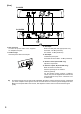
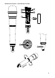
1. Power switch
Slide this switch towards “ON” to turn the
power on, and slide it again towards “OFF” to
turn off the power.
2. Power / Battery lamp
A green LED lights as long as the battery
capacity is sufficient. When the battery
capacity becomes low, the green LED starts
to flash.
3. Numerical LED display
Indicates the current channel number in
normal state.
In setting mode, the indicated channel
number flashes until registered.
4. Channel setting key [SET]
Used to select the channel (frequency). (The
frequency must be identical to that of the
receiver.)
5. Infrared (IR) port
Receive the infrared signal from the receiver.
6. PAD switch (S-4.10-HDX only)
This switch is used for microphone sensitivity
adjustment .The sensitivity can be decreased
by “H” (0dB), “L” (-10dB).
Note Never position the transmitter antenna
directly against the body or hand. This
will have the effect of reducing the
operating range considerably.
7. Battery compartment
Insert an AA battery according to (+ ) and (– )
indications on the battery compartment.
Note: Turn off the power switch.
HDX:
Hold the microphone body and rotate the
microphone grip counterclockwise to remove it.
BTX
:
Slide the battery cover in the
direction indicated by the arrow while pressing
on the cover with a thumb and hinge up-wards.
8. MIC / Instrument switch (BTX only)
Slide this switch towards “MIC” to connect the
microphone, and slide it towards “INST” to
connect the instrument.
9. Audio level control (BTX only)
Adjust the audio level control using the
suppli ed screwdriver. The transmitter
sensitivity increases as the control is rotated
clockwise, and decreases as rotated
counterclockwise.
10. Input connector (BTX only)
3.5 mm j ack socket, Connect the
microphone or the instrument cable.
11. Antenna (BTX only)
12. Clip (BTX only)
Clip the transmitter to a belt through the
transmitter clip. It is better the belt should
be pressed against the base of the
transmitter clip.
13. Microphone (BTX only)
Note: Route the microphone cable so as to
avoid undue strain of friction. Try and keep the
microphone cable away from the antenna.
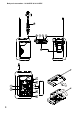
6. CHANNEL NUMBER
SETTING by MANUAL
Step 1. Press the SET key for about 3 seconds until the displayed channel number blinks.
Step 2. Select the desired channel number with the SET key, and once the desired number is
reached, release the SET key. After about 5 seconds, the receiver automatically sets
channel and the blinking number turns to steady light.
Tip Continuous or each depression of the SET key permits the display to cycle through the
channel numbers.
On the receiver side, when the dot LED by the channel number LED is blinking at
selecting channel number, this means that the channel has already been occupied.
Note Make sure that the transmitter is identical to the receiver in the channel number.
Should the microphone's setting differ from that of the receiver, the receiver does not receive the
radio signal from the transmitter.
On the transmitter side, the power switch turns on, the channel
number display turns on the light for about 30 seconds, and
then this display turns off the light. When SET key presses in
this condition, this display turns on the light for about 30
seconds.