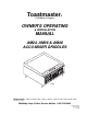
Toastmaster ® A Middleby Company OWNER'S OPERATING & INSTALLATION MANUAL AM24, AM36 & AM48 ACCU-MISER GRIDDLES AM24 Toastmaster® • 1400 Toastmaster Drive • Elgin, IL 60120 • (708)741-3300 • FAX (708)741-4406 A Middleby Company Middleby Corp 24 Hour Service Hotline 1-800-238-8444 Part No. 32025 Price $15.
Toastmaster ® GRIDDLE LIMITED WARRANTY All equipment manufactured by Toastmaster Commercial which is sold under the “Toastmaster” trademark and used for commercial purposes is warranted against defects in materials and workmanship. The warranty period runs 12 months from the original date of installation. This 12 month warranty period may not run beyond 18 months from the original date of purchase and is for the benefit of the original purchaser only.
IN CASE OF FIRE 1. De-energize griddle at disconnect switch. This will cut off power to the heating elements allowing griddle to cool. This reduces the flash point temperature making it easier to stop the fire. 2. Cover the affected area with a heavy blanket or canvas. Play the fire extinguisher nozzle over the blanket or cover to seal off air thus smothering the fire. CAUTION: Do not attempt to fight a grease fire by playing the nozzle of the fire extinguisher directly on the burning grease.
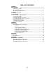
TABLE OF CONTENTS SECTION 1 DESCRIPTION ........................................................................................ 1 Component Location ................................................................................. 2 Specification Chart .................................................................................... 3 Electrical Specification Chart ..................................................................... 4 Dimension Drawing ..................................................
SECTION 1 - DESCRIPTION SECTION 1 DESCRIPTION ACCU-MISER (AM) SERIES GRIDDLES ARE: • Electrically heated • Counter top mounted • Heated by infrared emitter panels • Thermostat solid state controller MODELS: • AM24 (24" wide) • AM36 (36" wide) • AM48 (48" wide) INFRARED HEAT PANELS. The griddle employs infrared cooking technology. Infrared heat panels are placed below the griddle plate. These panels are 12" wide, which means an AM24 will accommodate 2 panels, an AM36 will accommodate 3 panels and etc.
SECTION 1 - DESCRIPTION Component Location Figure 1-2 2
SECTION 1 - DESCRIPTION NOTICE Toastmaster (Manufacturer) reserves the right to change specifications and product design without notice. Such revisions do not entitle the buyer to corresponding changes, improvements, additions or replacements for previously purchased equipment.
SECTION 1 - DESCRIPTION Griddle Electrical Specification Chart Voltage Total Loading kW/Phase kW Nominal Amps/Line Wire 3 Ph 3 Ph X-Y Y-Z X-Z X Y Z Minimum Supply Wire (AWG) Gauge* 1 Ph 3 Ph 1 Ph 3 Ph 1 Ph AM24 208 240 6.2 6.2 3.1 3.1 3.1 3.1 --- 15.0 13.0 26.0 22.5 15.0 13.0 30.0 26.0 10 10 8 10 25 30 30 30 AM36 208 240 9.3 9.3 3.1 3.1 3.1 3.1 3.1 3.1 26.0 22.5 26.0 22.5 26.0 22.5 45.0 39.0 10 10 6 8 25 30 40 45 AM48 208 240 12.5 12.5 6.2 6.2 3.1 3.1 3.
SECTION 1 - DESCRIPTION Griddle Dimension Drawing 5
SECTION 1 - DESCRIPTION NOTES 6
SECTION 2 - INSTALLATION SECTION 2 INSTALLATION A. Inspect for Shipping Damage All shipping containers should be examined for damage before and during unloading. This equipment was carefully inspected and packaged at the factory. The freight carrier has assumed responsibility for its safe transit and delivery. If equipment is received in damaged condition, either apparent or concealed, a claim must be made with the delivering carrier. 1.
SECTION 2 - INSTALLATION D. Installing Griddle on Accessory Stand. NOTE: If you are installing the griddle on a counter do not do Step D. Go directly to Step E. Accessory stands are available for all Accu-Miser Griddles. See the following Accessory Stand List. GRIDDLE ACCESSORY STAND LIST Griddle Model Number Accessory Number AM24 AM36 AM48 All Models 7324ES 7336ES 7348ES ACCS06J Description Stand. Mount on 6" casters not included. Stand. Mount on 6" casters not included. Stand.
SECTION 2 - INSTALLATION 3. Turn stand right side up and secure to griddle with 3/8-16 bolts and lockwashers as shown in Figure 2-2. NOTE: Be sure the casters with brakes are located at the front of the griddle.
SECTION 2 - INSTALLATION E. Electrical Connection Be sure your electrician provides the proper wire gauge with a capacity for carrying the voltage required. Wire capacity is listed on the serial number data plate. Wire capacity and electrical specifications are listed in Section 1 of this manual. Also check local and state codes for proper wire size. The incoming power wires from the circuit breaker box to the griddle are inserted into the rear or bottom of the griddle as shown below.
SECTION 2 - INSTALLATION F. Initially Clean the Griddle 1. Clean the rust preventive material from the griddle surface with a non-flammable grease solvent. 2. Wash the griddle with warm water and a mild detergent. 3. Rinse with a damp cloth and wipe dry. G. Test the Installation, refer to Figure 3-2 NOTE: The griddle must be initially cleaned as directed in Step F before completion of Step G. 1. Turn all rocker On/Off switches to the "Off" position. 2.
SECTION 2 - INSTALLATION NOTES: 12
SECTION 3 - OPERATION SECTION 3 OPERATION I. Location and Function of Controls The following information provides a basic description of the griddle operator components, their location and the function they perform.
SECTION 3 - OPERATION Figure 3-2 Control Panel A. CONTROLS All oven operating controls are on the control panel. • Thermostat Control Knob - The thermostat control knob is used to adjust the corresponding element section above it to your temperature requirements. The maximum set point is 450°F (232°C), the minimum set point is 150°F (65°C). • Heating Indicator Light - Located below each thermostat control the heating indicator light will be lit whenever the adjacent griddle section is calling for heat.
SECTION 3 - OPERATION B. Seasoning the Griddle 1. Preheat the griddle to 300°F (149°C) and spread a light film of unsalted cooking oil or fat over the surface with a soft cloth. 2. Allow griddle to stand this way for two minutes to give the oil an opportunity to work into the pores of the metal and to form a smooth coating over the outside. 3. Wipe off excess oil and repeat Steps 1 and 2 at 350°F (175°C). 4.
SECTION 3 - OPERATION b. At the end of each day of operation or at the end of each shift thoroughly clean the grease trough and the spout into grease drawer. c. Clean the griddle surface with a pumice or griddle stone by rubbing with the grain of the metal while the griddle surface is still warm. d. Wipe griddle clean of residue from the griddle stone 2. Cleaning the exterior - Wipe down sides of griddle and all areas around griddle to keep them free of splashed grease. a.
SECTION 3 - OPERATION F. Time and Temperature Guide NOTE: All cooktimes are approximate. FOOD CONTROL SETTING TIME IN MINUTES ADVANCE PREPARATIONS Canadian Bacon 350°F(176°C) 3 to 4 Slice (not too far in advance as meat will darken)-Split edges to prevent curling. Hamburgers 350°F(176°C) 3 to 4 Prepare recipe - Form patties - Separate with waxed paper - Refrigerate. Cheeseburgers 350°F(176°C) 3 to 4 A hamburger patty plus melt a slice of cheese on top just before serving.
SECTION 3 - OPERATION G. Cooking Capacities NOTE: All production capacities are approximate.
SECTION 4 - PARTS LIST SECTION 4 PARTS LIST 19
SECTION 4 - PARTS LIST Figure 4-1 Overall Exploded Drawing 20
SECTION 4 - PARTS LIST Parts List for Figure 4-1 Overall Exploded Drawing AM24 Item Qty # 1 2 3 4 5 6 7 8 9 10 11 12 13 14 15 16 17 18 19 20 21 21 22 23 24 25 26 27 28 29 30 31 31 32 33 34 35 1 4 1 1 1 1 1 1 4 2 2 2 2 2 2 2 1 2 2 1 2 2 2 2 2 2 8 2 1 1 2 2 n/a 2 2 2 2 AM36 AM48 Part # Qty Part # Qty Part # 30979 2000620 31183 30972 30977 30987 2700090 30976 3101908 31154 19A1S145 3003188 3A81D8801 3004290 3003993 97415 3003992 3004289 7007918 31160 7610644 7610831 7610637 2500132 7007920 31182 200
SECTION 4 - PARTS LIST NOTES: 22
SECTION 5 - SCHEMATICS SECTION 5 SCHEMATICS 23
SECTION 5 - SCHEMATICS 24
SECTION 5 - SCHEMATICS 25
SECTION 5 - SCHEMATICS 26
SECTION 5 - SCHEMATICS 27
SECTION 5 - SCHEMATICS 28
SECTION 5 - SCHEMATICS 29
SECTION 5 - SCHEMATICS For more information on the complete line of Toastmaster® products, contact your Food Service Equipment Dealer, or write to us at the address below. Toastmaster® A Middleby Company Middleby Corp 24 Hour Service Hotline 1-800-238-8444 Toastmaster® 1400 Toastmaster Drive Elgin, IL 60120 (708)741-3300 Part No. 3102549 Price $15.00 Printed in U.S.A.