TOHO ELECTRONICS INC. Multi-Channel Board Controller Detailed Manual Thank you very much for purchasing a Multi-Channel Board Controller. The Multi-Channel Board Controller outputs control signals that match an input from a thermocouple (a K/J thermocouple) or an input from a temperature input from a resistance bulb (Pt100/JPt100) to a predetermined setting. The product comes equipped with an RS-485 or an RS-232C for data communications with a host computer.
Contents 1. Operating precautions .......................................................................................................... 3 2. Names and functions of the components ............................................................................. 4 2.1 Product diagram......................................................................................................... 4 2.2 Names and functions .................................................................................................
1. Operating precautions When the product reaches you, please ensure that the product you have received is of the following model which you ordered. Model: TTM−00BT−①−R−② ① Input type ......................... 0: Thermocouple input 1: Resistance bulb input ② Communication type:....... M1: RS-485 M2: RS-232C To allow you to use the product safely, this detailed manual uses the following symbols: Warning: Mishandling despite this warning may result in the user's death, electric shock, burn, or other risk.
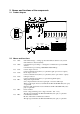
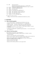
2. Names and functions of the components 2.1 Product diagram Event output Control output Temperature input Voltage input Communication Power CT input 2.2 Names and functions 2.2.1 SW1: 2.2.2 SW2: 2.2.3 CN1: 2.2.4 CN2: 2.2.5 CN3: 2.2.6 TB1: 2.2.7 TB2: 2.2.8 TB3: Unit number change --- Change product unit numbers with the rotary switch. Unit number: 0 to F (hexadecimal) Communication speed change --- Change the communication speed with DIP switches.
2.2.9 TB4: 2.2.10 2.2.11 2.2.12 2.2.13 2.2.14 2.2.15 2.2.16 2.2.
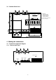
3.3 Outside dimensions 9-φ3.5 drill Sub-board 36 × 114.5 4. Making the connections 4.1 Terminal arrangement diagram 4.1.1 Thermocouple input Event output Control output Temperature input CT input Voltage input Communication Power 6 Board height • Thermocouple input 29.2mm maximum • Resistance bulb input 39.
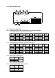
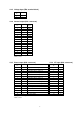
4.1.2 Resistance bulb input Event output Control output Temperature input Voltage input CT input Communication Power 4.2 Terminal arrangement 4.2.1 Temperature input (TB1: terminal block): For thermocouple input * For terminal numbers, see the carvings in the terminals. Terminal CH No. A1 1 B1 A2 2 B2 Terminal Terminal CH name No. + A3 3 − B3 + A4 4 − B4 Terminal Terminal CH Terminal name No. name + A5 + 5 − B5 − + A6 + 6 − B6 − Terminal CH No.
4.2.5 Voltage input (TB4: terminal block) Terminal No. 1 2 Polarity + − 4.2.6 Control output (CN1: connector) Connector No. 1 2 3 4 5 6 7 8 9 10 11 12 13 14 15 16 CH 1 1 2 2 3 3 4 4 5 5 6 6 7 7 8 8 Terminal name O.C COM O.C COM O.C COM O.C COM O.C COM O.C COM O.C COM O.C COM O.C.: open collector output COM: common 4.2.7 Event output (CN2: connector) Connector No. 1 2 3 4 5 6 7 8 9 10 11 12 13 14 15 16 4.2.8 CH Terminal name 1 2 3 4 5 6 7 8 1 2 3 4 5 6 7 8 Temperature alarm 1 output O.C.
4.3 Cautions on making the connections Warning • Before making the connections, turn off this product. Otherwise you may get an electrical shock. Warnings • This product will not begin control for about 10 seconds after being turned on. (It will not activate its outputs or other components.) Be careful if you wish to use the product as an interlocking circuit.
Parameter a) Identifier b) Name c) R/W d) Description and set range e) Remark Initial value (communication numerical data) TC, thermocouple; Pt, resistance bulb SV1 Setting R/W r/w R/W of the control settings Thermocouple input: Thermocouple K, 0.0 to 1300.0°C Thermocouple J, 0.0 to 800.0°C Resistance bulb input: PT100/JPT, -199.9 to 500.
Event output parameters a) Identifier b) Name c) R/W Temperature alarm output*functional setting R/W d) Description and set range e) Remark R/W of the temperature alarm output*functional setting *1 Initial value (communication numerical data) TC, thermocouple; Pt, resistance bulb E*F *: 1 to 8 000 * * PV temperature alarm functions Type 0 None 1 Deviation top/bottom limit alarm Additional functions Type 2 Deviation top limit alarm 3 Deviation bottom limit alarm 0 None 1 Hold 4 Deviation rang
Voltage input parameters a) Identifier b) Name c) R/W d) Description and set range e) Remark Initial value (communication numerical data) TC, thermocouple; Pt, resistance bulb DIF Set a voltage input function R/W R/W of the voltage input function setting Numerical data Function type When voltage is applied 00000 None 00001 SV/SV2 function SV2 00002 RUN/READY function READY 00003 Auto/manual function Manual 00004 Forward/reverse operation function Forward operation 00005 Auto-tuning
Monitor window parameters a) Identifier PV1 b) Name c) R/W d) Description and set range e) Remark Measurement R Used as a measurement monitor When over-scale: HHHHH (the same is true when the sensor has a wire break) When under-scale: LLLLL CT measurement R R of the measured current of the heater current detector When over-scale: HHHHH When reading is impossible: ----- DIM DI monitor R R of the voltage input monitoring 00000: State where voltage input is not applied 00001: State where voltage
Control parameters a) Identifier b) Name c) R/W d) Description and set range e) Remark Set an SV limiter top limit R/W R/W of the SV limiter top limit setting From the bottom limit to the top limit of the set range Provided that the difference from the SV limiter bottom limit setting is no less than 50 digits. For the range, see 7.1 on page 16.
Control parameters a) Identifier b) Name c) R/W d) Description and set range e) Remark Initial value (communication numerical data) TC, thermocouple; Pt, resistance bulb MH1 Set an operation quantity limiter, top limit R/W r/w R/W of the operation quantity limiter, top limit setting Set range: Operation quantity limiter, bottom limit setting to 100.0% Set an operation quantity limiter, bottom limit R/W r/w R/W of the operation limiter, bottom limit setting Set range: 0.
7. Function description 7.1 Display range and set range of temperature input 7.1.1 Display range and set range of thermocouple input (JIS C 1602 - 1995) Set range with a decimal point Display range with a decimal point Set range without a decimal point Display range without a decimal point K (JIS) 0.0 to 1300.0°C -40.0 to 1326.0°C 0 to 1300°C -40 to 1326°C J (JIS) 0.0 to 800.0°C -31.0 to 850.0°C 0 to 800°C -31 to 850°C 7.1.
7.5 Temperature alarm output 7.5.1 Temperature alarm output: Compare the measurements with the setting value of the temperature alarm output and turn on and off the temperature alarm output. • Operation table of temperature alarm outputs 5. Absolute value top/bottom limit 1. Deviation top/bottom limit E*C E*C E*C E*L △ SV 0C (°F)) 0℃( v E*H 2. Deviation top limit E*C E*L E*H 6. Absolute value top limit E*C E*C 0℃( v 0C (°F) ) E*H SV △ 3. Deviation bottom/limit E*H 7.
7.6 Heater wire break alarm output The output will be turned on if a heater wire break (no output even if the output is turned on) remains for at least 190mS. 7.7 SSR breakdown alarm output The output will be turned on if an SSR breakdown (there is output even if the output is off) remains for at least 190mS. 7.8 Error alarm output The output will be turned on in the case of a memory error, A/D error, or sensor error. 7.9 Communication 7.9.
7.9.3 Communications procedure This product returns a "response message" in response to a "request message" from a high-level computer. It therefore does not initiate a transmission. 上位コンピュータが 送信 上位コンピュータ 本器が 送信 上位コンピュータが 送信 要求メッセージ 要求メッセージ 要求メッセージ 本器 本器が 送信 応答遅延時間 0∼250ms 要求メッセージ 1ms以上 「2.8 応答遅延時間の設定」参照 「3.7.2 要求間隔」参照 「3.7.1 送受信タイミング」参照 7.9.
7.9.5 Composition of a request message (transmitted from a high-level computer to this product) n For codes ① to ⑧, see "7.9.9 Code description." n For specific examples of request messages, see "7.9.11 Examples of communications to be read" and "7.9.12 Examples of communications to be written.
7.9.6 Composition of a response message (transmitted from this product to a high-level computer) n For codes ① to ⑪, see "7.9.9 Code description." n For specific examples of request messages, see "7.9.11 Examples of communications to be read" and "7.9.12 Examples of communications to be written.
7.9.7 Composition of a memory bank function message n For codes ① to ⑫, see "7.9.9 Code description." n For specific examples of request messages, see "7.9.11 Examples of communications to be read" and "7.9.12 Examples of communications to be written." Note that the request is in lowercase characters. 1) Composition of a read request message S T □ □ X r E B □ □ □ □ T C X C ① ② ③ ④ ⑫ ―⑤― ⑦ ⑧ BCC data End code Identifier Memory bank No.
7.9.
7.9.9 Code description n Codes from ① STX to ⑫ memory bank function are expressed in ASCII codes. n For the ASCII codes, see "7.9.13. Table of ASCII codes." n For the procedure for conversion to ASCII codes, see communication examples 7.9.11 and 7.9.12. ① STX This code is necessary for the receiver to detect the top of a message. This is affixed to the top of the character string to be transmitted. ② Unit number This code is for a higher-level computer to identify the communication partner (this product).
⑧ BCC This is a check code for error detection and is the exclusive OR (EX-OR) of all characters from STX to ETX. ⑨ ACK It is an acknowledge code. If a message received by this product is error-free, this code will be incorporated in the "response message" from this product and returned. ⑩ NAK It is a negative acknowledge code. If a "request message" received by this product is error-ridden, this code will be incorporated in the "response message" from this product and returned.
7.9.10 Communications precautions 1) Communications timing Set a sufficient response delay to make sure that this product is switched over from transmission to reception with regard to a high-level computer in using communications. See "7.9.3 Communications procedure" and "7.9.2 3) Setting a response delay.
8) Storing data other than a store request message Store all parameters in the EEPROM in either of the three cases described below, even if no store request message is received. If auto-tuning is started and ends normally. (Provided that only PID constants are saved.) 9) Changing the settings (SV or SV2) by communications during auto-tuning Even if the settings (SV or SV2) used in control for auto-tuning are changed by communications, the settings (SV or SV2) will not be changed until the auto-tuning ends.
7.9.12 Examples of communications to be written Example: Request message: Requests that the temperature alarm output setting of EIF in channel 1 (High-level computer) of unit number 3 be changed to deviation top/bottom alarm + holding. In response to that, Response message: This returns a notice that the request message has been received. (This product) *Check that it has been correctly written by reading the data separately.
7.9.
4) Character : Start bit length ........................ Fixed at 1 bit : Stop bit length ........................ Fixed at 2 bit : Data length ............................. Fixed at 8 bit : Parity ...................................... Fixed at no : BCC check ............................. Fixed at yes : Unit number ........................... 0 to F (hexadecimal number) Set this with the rotary switch.
7.9.15 Communication wiring 1) Connecting the RS-485 line 上位コンピュータ ( 親局) High-level computer (parent stations) 本器( 子局) This product (mobile unit) T/R( A) T/R( A) T/R( B) T/R(B) 本器( 子局) This product (mobile unit) T/R( A) T/R(B) 本器( 子局) This product (mobile unit) T/R( A) T/R(B) Install an end of line resistor at both of the farthest devices in the parent station and the mobile unit. For a resistance value, use one that matches the characteristic impedance of the cable.
8. Specifications and ratings 8.
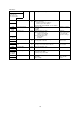
9. Maintenance and inspection Symptom Check item Inaccurate measurement Is the sensor normal? (Connect a different sensor to the line. Does it show a similar symptom?) Is the sensor correctly connected? Is the correct sensor type set? (Is the sensor the same as the type setting entered in the product?) Are all the PV correction values set to the correct levels? The setting does not match the measurement.
TOHO ELECTRONICS INC. Head office: 1-13-21, Tanashioda, Sagamihara Kanagawa 229-1125 Japan.