
User Manual


Table Of Contents
- TTM-200シリーズユーザーズマニュアル 英語 48-7009-D.pdfから挿入したしおり
- TOP
- Contents
- 2. Installation
- 3. Wiring
- 4. Basic operation
- 5. Operating the equipment
- 5.1 Precautions on operating the equipment
- 5.2 Operating monitor display
- 5.3 How to set run settings
- 5.4 How to set each function and description of function
- 5.5 Explanation of the program run function
- 5.5.1 Operation flow of the program run
- 5.5.2 SET 21 program function setting
- 5.5.3 SET 21 program function setting screen
- 5.5.4 SET 22 program setting
- 5.5.5 SET 22 program setting screen
- 5.5.6 Explanation of the screen display and operation of a program run
- 5.5.7 Complementary explanation of the program run
- 5.6 Explanation of the bank automatic switching function
- 6. Explanation on parameters
- 6.1 Input 1 type setting
- 6.2 Remote SV input type setting
- 6.3 Function key function setting
- 6.4 Control function setting
- 6.5 Output (from OUT 1 to OUT 7) type setting
- 6.6 Current transformer (CT) setting
- 6.7 DI setting
- 6.8 Timer function setting
- 6.9 Communication function setting
- 6.10 Initial setting
- 6.11 Priority screen setting
- 6.12 Bank function setting
- 6.13 PROGRAM FUNCTION SETTING
- 6.14 PROGRAM SETTING
- 6.15 BANK AUTOMATIC SWITCHING FUNCTION SETTING
- 7. Appendix
- 7.1 Product specifications
- 7.2 Accessories
- 7.3 Error (abnormality) display
- 7.4 Troubleshooting
- 7.5 Setting list
- 7.5.1 Run mode
- 7.5.2 Input 1 setting mode (SET 01)
- 7.5.3 Input 2 setting mode (SET 02)
- 7.5.4 Key function setting mode (SET 03)
- 7.5.5 Control setting mode (SET 04) (1/4)
- 7.5.6 OUT 1 and 2 setting modes (SET 05 and 06) (1/3)
- 7.5.7 OUT 3 to 7 setting modes (SET 07, 08, 09, 10 and 11) (1/2)
- 7.5.8 CT setting mode (SET 12)
- 7.5.9 DI setting mode (SET 13)
- 7.5.10 Timer 1 to 3 setting modes (SET 14, 15 and 16)
- 7.5.11 Communication setting mode (SET 17)
- 7.5.12 Initial setting mode (SET 18)
- 7.5.13 Priority screen setting mode (SET 19)
- 7.5.14 Bank setting mode (SET 20)
- 7.5.15 Program function setting mode (SET 21)
- 7.5.16 Program setting mode (SET 22)
- 7.5.17 Bank automatic switching function setting mode (SET 23)
48-7009-E 5-40
5.4.7 Current transformer (CT) abnormality function
■ What CT (current transformer) is
• CT is a function to detect that outputs are not properly turned on and off due to failure of relays or
SSRs.
• For detection of failure, using CT, ensure to wire the CT terminal and output terminal (such as heater
power supply), set the CT * target connection setting (CI *) and CT 1 abnormality current value
setting (Ct 1), and establish the control effective.
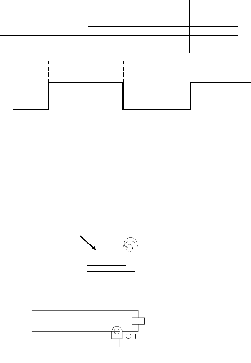
State of control output 1
Power distribution to heater
CT abnormality
state
Output *
Operation lamp
ON
Lighting
Existent *1)
Normal
Nonexistent (output disconnection state)
Abnormal
OFF
Extinction
Existent (output short state)
Abnormal
Nonexistent *2)
Normal
ON
Control output 1
Ton *3)
Toff *4)
OFF
*1) Power distribution existent (normal) is determined when the CT 1 abnormal current value setting
is larger than the CT current value in the period Ton.
*2) Power distribution nonexistent (normal) is determined when the CT 1 abnormal current value
setting is smaller than the CT current value in the period Toff.
*3) State of the output disconnection is not detected when the ON time (Ton) of the control output 1 is
300 ms or smaller.
*4) State of the output short is not detected when the OFF time (Toff) of the control output 1 is 300 ms
or smaller.
* Detection is unstable when the CT current value is small. To solve the issue, wind CT with load
wires passing through the hole multiple times as illustrated below. Winding twice results in the
detection current being larger by a multiplication factor of 2.
Note The detection accuracy is, however, deteriorated by a multiplication factor of 2.
CT
■ Example of installation, setting calculation and parameter setting of CT
■ Single phase
Install CT in the location illustrated below.
AC line
To equipment
CT input
Load
Load: heater and such
Note Wire in one way in any direction.
Load wire