
Installation Manual

" L " Bracket
(Option)
Out-swinging
7
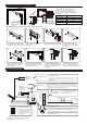
Put one rubber washer between
two washers, and place them over
the armature screw between the
armature plate and the door.
9
Screw the two self-tapping screws
in the slotted holes of the mounting
plate and adjust the position of the
mounting plate so that it and the
armature plate from a 90-degree
angle.
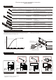
Tem pl ate
1
Fold the mounting template along
the dotted line to a 90-degree
angle.
door
Out-sw inging
Tem pl ate
2
Close the door, find a mounting
location on the door frame near the
upper free-moving corner of the door,
as close to the corner of the door
frame as possible.
3
Place the template against the door
and frame. Drill two holes in the frame
and three holes in door as indicated
on the template.
8
This will allow the armature plate to
pivot slightly around the armature
screw in order to compensate for
door misalignment.
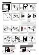
Regular Installation
4
Drill two holes in the frame and
three holes in the door as
indicated on the template.
6.8mm for M8-1.25 thread
16mm 8mm 12.7mm 8mm
Drill an 8 mm hole through
door, from sexnut bolt side
only, enlarge the 8mm hole
to 16mm.
Recommendation:
Micro EM-locks (300 LBS) maximum thickness of door is 44 mm.
Mini EM-locks (600 LBS) maximum thickness of door is 50 mm.
Midi EM-locks (800 LBS) maximum thickness of door is 48 mm.
Standard EM-locks (1200 LBS) maximum thickness of door is 46 mm.
Drill an 8 mm hole thru
door from sexnut bolt
side of door, drill 12.7mm
hole, 36mm in depth.
Drill an 6.8 mm dia.
Hole and tap for
M8x12.5 thread.
Hollow Metal Door
Solid Door Reinforced Door
36mm
5
Mounting the armature plate to
the door . Actual installation
varies according to door style.
Armature Plate
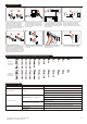
10
Once the position is correct, use
the screws to permanently mount
the mounting plate, And drill the
cable access hole.
Cable
12
Connect the power lead, and test
the unit.
Holding Force
Power
11
Use the Allen wrench to screw the
Fixing screws and Brass Sleeves
through the bottom of the
electromagnet into the mounting
plate.
Allen wrench
Finish
Insert the anti-tamper caps into the
mounting screw access holes. This
should be the last step, as once the
tamper caps are in place, they will
be difficult to remove.
With L bracket for narrow door frames
With U bracket for frameless glass doors
L bracket is used as extension
on narrow door frames to
provide adequate mounting
surface.
Universal glass door kits are
compatible with lock models,
except 1200 lbs serial.
Out-swinging
(Option)
UBK Bracket
UBK-008 for 8mm of glass door
UBK-010 for 10mm of glass door
UBK-012 for 12mm of glass door
UBK-014 for 14mm of glass door
4-2
6
Make sure the Guide Pins are in
the two guide pin holes.
Guide Pins
Installation Steps
Rubber Washer
Copyright Gianni Industries, Inc. All Rights Reserved.
P-MU-AM-EM Ver. G Publish:2007.11.07