
User Manual


14
ENGLISH
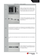
11
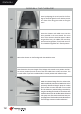
Now perform the same steps at the front of the servo lever, aer you pulled the wire
through the openings in the fuselage back. Provide a small preload of both ropes with
neutral rudder and servo horn. Then the crimp sleeves are pressed by pliers.
12
By further screwing the eyebolt into the clevis you now increase the tension of the
cables.
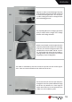
13
For the electrical connecon fuselage / wing
we recommend the 6-pin Mullplex connec-
tors, which can be either loose or permanent-
ly installed. The xed installaon requires a bit
more eort at the beginning, but facilitates
the assembly of the SWIFT later on the aireld
enormously.
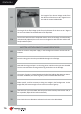
14
Solder the approx. 50cm long servo cable to the
contacts of the MPX connectors.
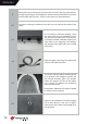
15
The receiver and the baeries should be placed
as far forward in the fuselage as possible and
well secured. Therefore, glue in the wooden
baery tray supports and and x the baery
tray by screws. The baeries can be xed by
velcro and velcro loops.
Nevertheless, addional trim weight is needed
to reach the center of gravity.
16
Oponal: The installaon of a towing coupling
can be done directly in the nose or approx.
25cm further to the back of the fuselage at its
own discreon.