UNIVERSAL TOOL TABLE 240-1575 Owner’s Manual PRODUCT SPECIFICATIONS Work station tabletop size: 14” x 25” MDF lower shelf 18” x 27” Working height 32” Max. weight capacity 500 lb.
TABLE OF CONTENTS Product Product specifications……………………………....………………... ……………............. 1 Table of contents…………………………………………..……………....…..…................ 2 Safety instructions……………………………………….... ……………....…………...…. . 3 Safety symbols…………...……………………………….... ……………....…………….. . 4-6 Description……………………………………………….... ……………....…...…………. . 6 Assembly………………………………………………….... ……………....……………… 7-8 Operation……………………………………………….... ……………....………………… 9-11 Maintenance………………………………………….... ……………....……………………..
SAFETY INSTRUCTIONS GENERAL SAFETY RULES WARNING: Read all safety warnings and instructions. Failure to follow the warnings and instructions may result in electric shock, fire and/or serious injury. Save all warnings and instructions for future reference. READ AND SAVE THESE INSTRUCTIONS WARNING: Do not modify this tool and/or use it for any application other than that for which it was designed. Do not use for scaffolding or as ladder.
SAFETY SYMBOLS WARNING: Be sure to read and understand all safety instructions in this Operator’s Manual, including all safety alert symbols such as “DANGER”, “WARNING”, and “CAUTION” before using this tool. Failure to following all instructions listed below may result in electric shock, fire, and/or serious personal injury. SYMBOL MEANING SAFETY ALERT SYMBOL: Indicates DANGER, WARNING, OR CAUTION. May be used in conjunction with other symbols or pictographs.
SAFETY SYMBOLS SAVE THESE INSTRUCTIONS Some of the following symbols may be used on this tool. Please study them and learn their meaning. Proper interpretation of these symbols will allow you to operate the tool better and more safely.
SAFETY SYMBOLS No-Hands Symbol Failure to keep your hands away from the blade will result in serious personal injury. No-Hands Symbol Failure to keep your hands away from the blade will result in serious personal injury. No-Hands Symbol Failure to keep your hands away from the blade will result in serious personal injury. Hot Surface To reduce the risk of injury or damage, avoid contact with any hot surface. DESCRIPTION KNOW YOUR WORK STATION (Fig.
ASSEMBLY WARNING: If any parts are broken or missing, do not attempt to operate the work station until the broken or missing part is replaced. Failure to do so could result in serious injury. WARNING: Do not attempt to modify this work station or create accessories not recommended for use with this work station. Any such alteration or modification is misuse and could result in a hazardous condition leading to serious injury. UNPACKING This product has been shipped disassembled.
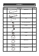
ASSEMBLY Item Description Qty. G Tabletop, rear 1 H Tabletop with scale, front 1 J Shelf 2 K Pan head screw (M6x10) 24 L Nut (M6) 24 M Countersink screw (M8x40) 1 N Nut (M8) 2 P Pad 1 Q Washer 8mm 1 R Pan head wood screw (ST5.
OPERATION WARNING: Do not use this tool for scaffolding or as a ladder. Make sure to tighten all screws securely prior to use. Maximum capacity is 500lbs. ASSEMBLING THE LOWER AND UPPER CROSS BRACES TO THE LEGS NOTICE: Use pan head screws(K) And nuts(L) to assembly all components except the tabletop and leveling device. NOTICE: Initially, loosely assemble the metal components. Fully tighten components at the end of the assembly process. 1. Assemble a long upper cross brace (A) to the two legs (E) (Fig.
OPERATION ASSEMBLING LEVELING DEVICE (Fig.5) Assemble the leveling device into one of the footpads. 1. Insert countersink screw (M) into pad(P). 2. Thread countersink screw (M) with pad (P) into first nut (N). 3. Place washer (Q) and second nut (N) on top of footpad (F). Thread countersink screw (M) through footpad (F), washer (Q), and second nut (N). Attach Footpads Slide one footpad (F) onto the bottom of each leg. (One footpad will include the leveling device.
OPERATION 2. Place the assembled frame upside-down onto the table tops. Thread the pan-head wood screws (R) with washers (S) through slots in the brace and into the five holes in each tabletop. NOTICE: The center screws lock the tabletops in position and have one washer (S) on the screw head and one additional washer (S) between the long upper cross brace and the tabletop (Fig.9). ASSEMBLING THE SHELF (Fig.
MAINTENANCE WARNING: When servicing, use only identical replacement parts. User of any other parts may create a hazard or cause product damage. GENERAL MAINTENANCE Avoid using solvents when cleaning plastic parts. Most plastics are susceptible to damage from various types of commercial solvents and may be damaged by their use. Use clean clothes to remove dirt, dust, oil, grease, etc. WARNING: When servicing, use only identical replacement parts.
EXPLODED VIEW
PARTS LIST No Part No Part Name QTY 1 240-1575-1 Short upper cross brace 2 2 240-1575-2 Long upper cross brace 2 3 240-1575-3 Short lower cross brace 2 4 240-1575-4 Long lower cross brace 2 5 240-1575-5 Leg 4 6 240-1575-6 Pan head screw( M6x10) 24 7 240-1575-7 Nut (M6) 24 8 240-1575-8 Footpad 4 9 240-1575-9 Pad 1 10 240-1575-10 Countersink screw (M8x40) 1 11 240-1575-11 Nut (M8) 2 12 240-1575-12 Washer ø8mm 1 13 240-1575-13 Pan head wood screw (ST5.
TOOL SHOP® UNIVERSAL TOOL TABLE WARRANTY 1-YEAR LIMITED WARRANTY: This TOOL SHOP® brand tool carries a 1-Year Limited Warranty to the original purchaser. If the tool fails within one (1) year from the date of purchase, simply bring this tool with your original sales receipt back to your nearest MENARDS® retail store.