
Use And Care Manual


NOTE: The 3/16" hex wrench and combination square are not included.
ALIGNING MITER AND BEVEL
MAINTENANCE
7
Fig. 1
Fig. 2
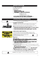
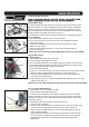
Aligning Miter Angle
1. Lower the head assembly and push in the lock pin to lock in the lower position.
Make sure table is in 0° detent and tighten miter lock knob. Place a combination
square (1) against the fence(2) and next to the blade (3) as illustrated. Locate
the square properly so it does not contact the tooth of saw blade. The saw blade
should contact the full length of the square. (Figure 1)
2. If blade does not fully contact the square, follow the fence alignment procedure.
Fence Alignment
a. The head assembly should remain in lowered position.
b. Use a 3/16" hex wrench, loosen the hex cap screws (4)(Figure 2) behind
c. Adjust fence until blade and the fence have full contact with the square.
d. Tighten hex cap screws.
1
2
3
4
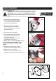
Aligning Bevel Angle
0° Blade Aligning
1. Rotate table to 0° position and lock in place.
2. Lower the blade and engage the lock pin.
3. Use a combination square to check blade squareness to table. Place the square
on the table and press it against the blade. If the blade does not contact the full
length of the square follow the alignment procedure.
a. Loosen bevel lock handle.
c. When you have established the vertical stop correctly, tighten the hex lock
nut (5) down to hold the setting.
d. Adjust bevel indicator (7). Loosen screw (8) and align indicator (7) to the 0° mark
Tighten screw (Figure 3)
45° Left or Right Blade Aligning
1. Rotate table to 0° position and lock in place.
2. Lower the blade and engage the lock pin.
3. Loosen bevel lock handle and tilt the head assembly to 45° bevel. The bevel
indicator should be on the 45° mark, the 45° bevel stop should be in full contact
with the 45° bevel stop screw, and the blade should contact the full length of the
combination square.
4. If the blade is not 45°with the table, adjust 45°bevel stop.
a. Loosen bevel lock handle.
c. When you have established the 45° stop correctly, tighten the hex lock nut
down to hold the setting.
d. Check that bevel indicator (7) is pointing to the 45°mark on the bevel scale.
If not,
first recheck the blade squareness to the table and 0° bevel indicator
alignment.Then, repeat the 45° blade alignment and make appropriate
adjustments.
fence (2). (Figure 1)
b. Using an 11/32" open-end wrench to loosen the hex lock nut (5) and then using a
3/16" hex wrench to adjust the hex screw (6) up or down. (Figure 3)
b. Use an 11/32" open-end wrench to loosen the hex lock nut (9) and then use a
3/16" hex wrench to adjust the hex screw (10) up or down. (Figure 4)
NOTE: The 11/32" open-end wrench and 3/16" hex wrench are not included.
e. Adjust the miter indicator(9 Figure 4). Loosen screw and align indicator
7
8
5
6
Fig. 3
9
10
Fig. 4
to the 0° mark.(Fig.1)