
Instruction Manual


If, for any reason, you choose not to use Fabrikote for covering
your Cub, we recommend that you use some kind of fabric cover-
ing, such as silk and dope. CLOTH COVERING IS RECOM-
MENDED ON THIS MODEL.
ENGINE AND COWL MOUNTING
1. Use a few drops of cyanoacrylate glue to mount your engine
temporarily to the motor mount, in the approximate position
shown on the plans. Turn the fuselage so that the firewall is
pointing straight up. Set the engine and mount on the firewall
about where it is shown on the plans, except turn the cy-
linder head of the engine so that it is inverted instead of side-
mounted. Slip the cowl over the engine and on the fuselage.
On some types of engines, it may be necessary to remove the
needle valve.
If the engine is sticking too far out of the cowl opening or is
not sticking out far enough, remove the cowl and reposition
the engine on the mount to correct. Once you have the
engine on the mount where you want it and the cowl down
over the nose of the fuselage where it will finally fit, remove
the cowl and use the engine's position on the mount to mark
hole locations for mounting the engine to the motor mount.
Remove the engine.
2. The typical .40 engine requires the use of No. 4 x 5/8" sheet
metal screws (not furnished) to mount the engine to the
motor mount. Use a 3/32" dia. drill bit and accurately drill
the motor mount with four guide holes. Next it will be
necessary to pre-tap these holes with a No. 4 x 5/8" sheet
metal screw. Use some oil on the screw and in the holes to
assist in the thread cutting.
3. Bolt the motor mount, without engine, in place on the fire-
wall. If you are using a muffler, attach it to the engine at this
time
along
with
the
needle
valve,
and
anything
else
that
might be left off. Using the plans as a rough guide, CARE-
FULLY begin to cut-out the right side of the cowl. The use
of a hand held grinder is the quickest way to do this. En-
large this hole gradually until you can fit your engine through
the cowl and set it on the motor mount while the cowl is
held in place with tape or by hand. Once you are satisfied
that the hole is adequate and enough clearance is left around
the engine, the edges of the cut-out can be cleaned-up and
smoothed with light sandpaper. Remove the cowl from the
fuselage.
4. Three (3) 1/2" x 1/2" x 1/2" hardwood cowl-mounting
blocks are provided. These must now be epoxied in place on
the firewall as shown on the plans. Different engine set-ups
may require that these be moved to other locations. This is
no problem, as long as they roughly represent a triangular
mounting for the cowl. It is important that these blocks be
epoxied in place at the edge of the fuselage sides at the fire-
wall. Too far inside the edge will allow the mounting screws
to distort the cowl when they are tightened in place.
Slip the cowl over the front of the fuselage and then tempo-
rarily mount the engine with at least two screws so that it is
flat against the mount arms. Position the cowl on the fuse-
lage so that it is properly clearing the engine and drive washer
and is square, both from the side view and the top view. Use
masking tape to hold the cowl firmly in position.
Hold the nose of the fuselage to a light source, such as a bare
light bulb and the mounting blocks can be clearly seen thru
the light yellow plastic. With a pencil, mark a hole location
directly over each mounting block, in the approximate center
of it. With a nail or other sharp object, mark and pre-punch
each of the three pencil marks on the cowl. With a 1/16" dia.
bit, drill each of the three mounting holes through the cowl
13
and mounting blocks. Screw the three No. 2 x 1/2" cowl
mounting screws in place and remove the tape holding the
cowl to the fuselage. Slip the engine in place to be sure the
cowl is correctly in place. If tightening the cowl mounting
screws tends to force the cowl inward (distortion), that
particular mounting block should be shimmed with a scrap
piece of plywood to close the gap.
5. With the cowl removed and the engine in place, mark the
fuel line and throttle line holes. Remove the engine and drill
these holes.
6. The throttle servo can now be installed in the fuselage. The
location of this servo can vary as long as the access to it is
maintained and it's action does not interfere with the fuel
lines or the tank itself.
7. The fuel tank and fuel lines should be installed carefully to
ensure correct fuel feed. The tank itself should be surrounded
by foam rubber to keep it from "foaming" and to keep it in
place on the tank tray.
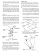
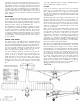
PRE-FLIGHT ADJUSTMENT AND RIGGING
Attach the wing panels and struts to the fuselage. It is NOT nec-
essary to overtighten the wing bolts, just snug them in place.
With everything attached, stand back and view the airplane head-
on. If one wing appears to be low, adjust the strut clevises (both)
to correct. Once the wing panels appear the same and are square
with the stabilizer and rudder, proceed to the next step (see
diagram below).
Now turn the airplane so that you can view it from the side.
Sight down the wing panel facing you to determine if the bottom
of the wing at the tip is on the same plane as the bottom of the
wing at the fuselage. Initially, you should adjust either the for-
ward or rear strut (they act independently) to achieve the same
plane with both the inboard and outboard wing sections (see
diagram below).