
Manual
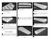


allow for free movement of the pushrod and
clevis. Securely snap a nylon clevis onto the
bellcrank. Feed the wire assembly into the wing
and screw the threaded end well into the clevis.
Hint: The wire is extra long. After the threaded
end starts threading into the clevis, you may bend
over the excess wire and use it as a handle to
turn the wire the rest of the way into the clevis.
Be sure to hold the clevis securely with pliers
while threading the wire into it to keep from
stressing the clevis pin. Cut off the excess wire
flush with the root end of the spar.
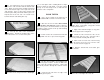
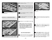
31. Use the die-cut plywood 93 deg. tool
(93) as shown to mark the ends of the spars and
TE’s.
NOTE: When marking the spars, the
corner of the tool is on the wing
centerline. When marking the TE
spars and flap LE’s, the corner of the
tool is positioned where the TE spars
end on the plan.
DO STEPS 32 AND 33 IF YOU ARE BUILDING
OPERATING FLAPS.
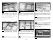
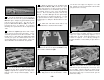
32. Glue the die-cut 1/8" plywood Flap
Horn Base (FH) in its place between W-2 and
W-3. Note how it is flush with the upward facing
edge of the ribs.
33. Cut pieces approximately 1" long from
the 1/2" x 3/4" x 12" balsa stick provided to act as
flap hinge blocks. These are shown on the right
wing panel plan. Some custom fitting of these,
such as tapering, is required. Skip to step 36.
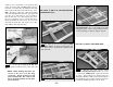
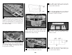
DO STEPS 34 AND 35 FOR FIXED GEAR.
34. Glue the 1/2" x 3/4" x 6-3/4" slotted
hardwood Landing Gear Rail and the 1/2" x 3/4"
x 1-1/2" maple LG Block with a generous amount
of epoxy. Their locations are shown on the left
wing panel drawing. Drill a 3/16" hole through the
rail and block at the location shown on the plan,
to allow the landing gear wire to be inserted.
- 17 -