TM WARRANTY..... Top Flite Models guarantees this kit to be free of defects in both material and workmanship at the date of purchase. This warranty does not cover any component parts damaged by use or modification. In no case shall Top Flite's liability exceed the original cost of the purchased kit. Further, Top Flite reserves the right to change or modify this warranty without notice.
TABLE OF CONTENTS METRIC CONVERSION CHART..............2 INTRODUCTION.......................................3 Precautions ............................................3 DIE PATTERNS .......................................4,5 DECISIONS YOU MUST MAKE ...............6 Engine and Mount Selection ..................6 Retracts ..................................................6 Wheel Selection .....................................6 Flaps.......................................................6 Drop Tank ............
WARNING! THIS IS NOT A TOY! The model you will build from this kit is not a toy! It is capable of serious bodily harm and property damage. IT IS YOUR RESPONSIBILITY AND YOURS ALONE to build this kit correctly, properly install all R/C components to test fly the model and fly it ONLY with experienced, competent help in accordance with all safety standards as set down in the Academy on Model Aeronautics Safety Code.
DIE-CUT PATTERNS -4-
DIE-CUT PATTERNS -5-
NOTE: We, as the kit manufacturer, can provide you with a top quality kit and great instructions, but ultimately the quality and flyability of your finished model depends on how you build it. Therefore, we cannot in any way guarantee the performance of your completed model, and no representations are expressed or implied as to the performance or safety of your completed model. scale power.
SUGGESTED SUPPLIES AND TOOLS ❑ ❑ ❑ ❑ ❑ ❑ ❑ ❑ ❑ ❑ ❑ ❑ ❑ ❑ ❑ ❑ ❑ ❑ ❑ ❑ ❑ ❑ ❑ ❑ We recommend only Top Flite Supreme™ glues for the assembly of our models. 2 oz. CA [thin] (TOPR1003) 2 oz.
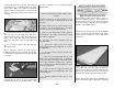
The most serious deviation is in the rear portion of the canopy. The rear window recesses (White ABS plastic in the model kit) were removed from the full scale aircraft. This is presumably to allow for a passenger. If you plan to enter serious competition, you will probably want to modify your kit to eliminate these panels. We chose to have the kit build as a stock P-40E. The P-40 was equipped with a variety of guns. The guns in the photos differ from the ones on the 3-view.
❑ 4. The stab and fin Leading Edges (LE’s) are cut to length from the 1/4” x 30” tapered balsa stock. Cut two pieces about 1/4” longer than the length shown on the plans for the stab LE. ❑ ❑ 7. Center the TE vertically on the back edge of ribs S-2 and S-5. Glue it in place with CA. HINT: Bevel the front edge of the stab and fin ribs to match the sweep angle of the LE stock. This will give you a better fit and a stronger glue joint. ❑ 11. Repeat steps 5 through 10 to build the left half of the stab.
fit to the stab LE’s. Place the Stab Joiner into the slots in the two S-1’s and work the whole assembly into position. Make sure all parts are properly aligned and the S-1 rib jig tabs contact the work surface. Glue in the Stab Joiner and the S-1’s using CA. the TE, if required, to have a smooth transition from the ribs. TIPS FOR MAKING WING AND STAB SKINS A. Wherever practical, pre-join the balsa sheets to make a “skin” before attaching them to the structure. ❑ 18.
blend the LE and TE to the ribs as you did before and sand the bottom edges of the ribs lightly with a T-bar sander. Check all glue joints, adding glue as necessary ❑ 24. True up the ends of the stab with a sanding block. Round the leading edge of the stab to match the cross section on the plan. ❑ 27. Cut away the skin at the center of the stab at the LE and TE as shown in the photo BUILD THE FIN ❑ 22. Cut two 1/4” wide strips off the end of a 1/16” x 3” x 30” wing sheet.
❑ 9. Blend the LE to match the ribs on the upward facing (left) fin side. Sand the TE, if necessary, to blend smoothly with the ribs. a sanding block. Shape the LE to match the crosssection on the plans. ❑ 10. Make a skin for each side of the fin using the 1/16” balsa sheet left over from the stab skins. Make the skin so it overhangs past V-1 about 1/2”; this will allow fitting to the stab later. See the sketch on page 11. ❑ 4. Pin ribs V-1 and V-4 to the building board over their proper locations.
block to “rough in” the shape of the elevators. Trial fit the elevators to the stab for final shaping. ❑ ❑ 10. Place the elevator over the plans and mark position of the 5/8” x 5/8” x 11/16” balsa Counter Balance Block on the elevator LE. Glue the Counter Balance Block in place. Shape the front of the block to a full radius. Allow approximately 1/16” clearance on both sides of the counter balance block in the stab opening. ❑ ❑ 2.
❑ 2. Draw a centerline on the aft surface of the LE. Draw two parallel lines 1/16” away on both sides of the centerline. ❑ ❑ 6. Center the 1/4” x 3/4” x 2” balsa rudder Balance Tab LE on the top of the rudder plate. Glue it with CA. ❑ ❑ 7. Glue a 1/4” x 1/4” x 1-3/4 stick balsa Rudder Tip to each side of the top of the rudder plate. 4. Align the Rudder Base over the plans and mark the “Rib” locations on both sides of the Rudder Base. ❑ 5. Hold the Rudder Base centered on the rudder LE.
sections on the plans to obtain the shape of the rudder. Use a razor plane and sanding block to “rough in” the shape of the rudder. Final shaping and fitting should be done after the fin is glued onto the fuselage, but you may wish to tape the rudder to the fin at this point to blend the upper ends of both. NOTE: The top edge of the FWD TRAILING EDGE AT AILERON curves more than the bottom edge at the tip. Since the wing is being built upside down, the more curved edge faces down next to the plans. ❑ 4.
order of the parts (e.g. 4C, 4, 4B, 4D.) Use CA+ to glue the parts together. Be sure to make a left and a right of each rib assembly. ❑ ❑ 15. When the TE At Flap is fitting in place well, with all of the rib TE’s aligned, glue it in with CA+. ❑ 9. Enlarge the pushrod hole in each W-8 until it is a 5/16” x 5/16” square hole. This will provide clearance for the clevis. ❑ ❑ 12. Glue the aileron trailing edge assembly to the aft edge of ribs W-8 through W-12.
Brace into the corner of W-8 and the Trailing Edge. ❑ ❑ 18. Work the Upper Spar assembly into place, making sure it fits well. Put some weights on top of the structure to make sure it is held onto the work surface. Fit the die-cut 1/16” plywood Fwd and Aft LG Box Webs between W-3 and W-4 to confirm the angle of these ribs. Use CA to glue in the top spar. Thoroughly glue the Fwd and Aft LG Box Webs to the spars as well as W-3 and W-4. ❑ ❑ 20.
❑ ❑ 25. Trim the 1/16” balsa Shear Webs to fit behind the spar between ribs W-4 through W-12. Glue them in place with CA+. Wick CA- into all the joints of the Shear Webs and the Spars to make sure they are well bonded. It is not important to glue the shear webs to the ribs. ❑ ❑ 26. Cut a 13” length of Outer Pushrod Tube. Rough up the outside of the tube with 220 grit sandpaper. Feed the tube through the holes in the ribs as shown on the plans. Use CA to glue the tube in place. ❑ ❑ 28.
INSTALL THE CENTER TE BLOCK Do steps 1 and 2 if you are NOT building operating flaps. ❑ ❑ 33. Glue the 3/8” x 1-3/16” x 2-1/2” balsa Center LE Block to the front of W-1 and the LE. Cut a V-notch in the Center LE Block centered on the dowel notch in W-1. This notch will assist you in drilling for the dowel later. ❑ ❑ 2. Draw a centerline down the 1/16” x 1” x 19” plywood TE Strip. ❑ ❑ 1. Glue the 3/8” x 1/2” x 1-1/4” Center TE Block to the TE of rib W-1 and the Flap TE. ❑ ❑ 2.
with the W-1 rib and the Flap Tip Rib. ❑ ❑ 5. Place the TE Strip with the beveled and centerline-marked side down on a very flat table. Glue a TE Jig Strip to the TE Strip. The jig strip will keep the TE straight until the wing is complete. Do not use excessive glue because it will have to be sanded off later. ❑ ❑ 7. Cut the die-cut 3/32” balsa Flap Tip Rib in half along its centerline. Align half of the rib over the plans and glue it in as shown in the photo. ❑ ❑ 10.
❑ 5. Drill two 1/4” holes in the shaped 1/4” plywood Wing Bolt Plate at the locations shown on the wing plan. ❑ ❑ ❑ 12. Cut the 5/8" X 5/8" X 6" balsa stick into six equal blocks. Fit and glue these Flap Hinge Blocks in place where shown on the wing plan. 2. Cut away the portion of rib W-1 around the spars as shown in the photo. This will allow the dihedral braces to pass through. ❑ ❑ 13 Mark the locations of the hinge blocks on the TE to help you find them later. ❑ ❑ 14.
Place the 3/8” x 2-5/8” x 10” balsa Wing Jig Block under W-1. The W-1 jig tabs and the spar at W-1 should contact the Wing Jig Block. The W-12 jig tabs and the spar at W-12 should contact your flat work table. ❑ 14. Drill out the outer hole in the bellcranks with a 5/64” drill bit. Test fit the pushrod into the bellcrank. FIXED LANDING GEAR ASSEMBLY Do the following six steps to make a left and a right fixed gear assembly. ❑ 11. Drill a 3/16” pilot hole through the wing LE for the 5/16" Wing Dowel.
❑ ❑ 2. Remove the Rails and drill the locations you marked with a 7/64” bit. ❑ ❑ 3. Test fit the bent Landing Gear wire through the Landing Gear Plate. Chamfer the hole in the plate for the wire, if required, until the wire will lie fairly flat on the plate. ❑ ❑ 6. Mark the locations for the #4 screws. Drill 3/32” pilot holes at the locations you marked. Screw the parts together with #4 x 1/2” Sheet Metal Screws. MOUNT THE LANDING GEAR Do the following eight steps for Retract and Fixed Gear. ❑ ❑ 3.
from the spar forward with one skin (2 skins for the bottom because of the landing gear bay). You will then sheet the wing from the spar back with another skin. This technique is a good compromise between sheeting the wing with individual sheets, and making one complete skin for the entire wing panel. It allows you to presand all of the seams that are over open structure and it is easier to align and glue than a complete one-piece skin. their alignment. View the struts from the front of the wing.
❑ 7. Use the leftover sheet from the previous step to sheet the forward portion of the wing outboard of W-4. ❑ 10. Tape the skin to the bottom of the wing structure so it is aligned along the spar. Make sure it fits well, especially at the root rib (W-1). Remove the skin from the structure. ❑ 11. Apply a bead of CA+ to all of the structure the skin will touch. ❑ 14. Use a punch to mark the hole locations in the bottom wing skin for the wing bolts.
❑ 7. Check the fit of the forward skin to the wing structure. Make adjustments if required. ❑ 13. Cut adequate clearance holes for the wing bolts in the top wing skin. ❑ 8. Apply a bead of CA+ to the wing structure and glue the forward wing skin in position. WING COMPLETION ❑ ❑ 4. Slide the die-cut 1/8” Plywood LE Jig over the dowel. 1. Trim the sheeting where it protrudes past the edge of the structure. It is preferred that you trim the tip of the wing sheeting to the center of rib W-12.
❑ 5. Apply 1/16” balsa sheeting to the tip section. ❑ 6. Glue the shaped 5/8” balsa Tip TE Block to the aft part of the wing tip. 3. Cut the Aft Flap Section from 1/16” x 1” x 18-1/2" plywood. Match the Aft section edge to the balsa forward section edge. Sand the edges for a clean match. ❑ ❑ ❑ 7. Square off the tip of the wing with a T-bar. ❑ 8. Glue the shaped 1” balsa Wing Tip to the tip of the wing as shown on the plans. ❑ 7. Cut 2-3/4" flap ribs from the 3/32” x 3/8” x 30” balsa sticks.
❑ 14. Glue the die-cut 1/8” plywood Flap Horn Plates to the flaps at the locations shown on plans. Note: These are located in different bays on the right and left flaps. BUILD THE AILERONS ❑ 11. Place the TE on the edge of the work surface. Use a sanding block to feather the edge of the birch TE to approximately 1/32” thick. HINT: The TE will change color from light to dark to light when properly sanded. ❑ 12.
allow proper aileron travel (refer to the crosssection at rib W-10 on the wing plan for the correct shape). ❑ 2. Inspect the two fuselage sides. Choose the Right and Left sides so the best surfaces will face outward. Mark the inside of the appropriate part RI and LI (for Right Inside and Left Inside.) ❑ ❑ 9. Tape the aileron to the wing and blend the aft portion of the wing tip and the aileron to create a smooth transition. IMPORTANT NOTICE: Compare the two die-cut 1/8” Plywood Fuse Doublers.
NOTE: It is helpful to keep some weight on the crutch while building the fuselage to keep it flat on the building board. ❑ 10. Place the Left Fuselage side in position. Make sure its edge is down on the building board and tack glue it at the following places: the lock notch near the front of the crutch; the edge at the front of the wing saddle; the top of F-2, F-3, and F-4. ❑ 13. Place the die-cut 1/8” plywood Former F1B between the fuselage sides. Check fit of the Chin Plate.
Fuselage Bolt Blocks into the notches in the fuselage side doublers at Former F-4. Use epoxy to make a small fillet around the sides of the bolt blocks. Also make an epoxy fillet between the bolt block and Former F-4. view to make sure they match up well. Silver solder the brass tube to the wire (see below). ❑ Use this process when soldering metal to metal such as brass tube to wire, or pushrod ends to wire. 16. Use CA+ to finish gluing the fuselage sides to Formers F-1B, F-2, F-3 and F-4.
❑ 30. Slide 5/16” lengths of Inner Pushrod Tube over the 32” pushrod wire. Space them approximately 2” apart. See the side view of the plans for proper spacings. ❑ 34. Screw the 3-1/2” piece of pushrod into the open end of the Nylon Ball Link. Position the brass coupler end so that it is inside the fuselage. Check the plans for the proper bend in the pushrod and bend to match. ❑ 31. Insert the pushrod wire into the rudder outer tube and snap the ball link on the tail wheel steering arm. ❑ 26.
❑ 2. Use the die-cut 1/8” plywood Dash Gauge (DG) to set the angle of the die-cut 1/8” Former F-3B. Glue Former F-3B securely at set angle. Do not glue in the dash gauge. rotated about the intersection of the lines shown, which indicate the engine centerline. ❑ NOTE: If you use the included adjustable engine mount, place it on the engine to determine proper spacing. You should use the 4 holes indicated by the punch marks on F-1A regardless of the width the mount is adjusted to.
❑ 14. Bend the sheeting around so it conforms with F-1. Apply some additional CA to the joint. ❑ 15. Trim the sheeting to the edge of the stringers along the top edge of the forward deck. ❑ 19. Test fit the two die-cut 3/32” balsa Upper Aft Fuselage Side sections together and make any necessary adjustments. Glue the two pieces together and lightly sand both sides. ❑ 16. Sand the sheeting and the stringers to match the flat tops of formers F-1, F-2 and F-3. ❑ 17.
❑ 25. Glue the Upper Aft Fuse Sides at their bottom edge only with CA. ❑ 26. Moisten the Upper Aft Fuse Sides with a damp paper towel. Form both the right and left Upper Aft Fuse Sides against the formers and hold in place with long strips of masking tape. ❑ 27. Glue the Upper Aft Fuse Sides to the formers and stringers. ❑ 31. Glue the aft portion of the Aft Deck Top to the fuselage. Use a razor plane and sanding block to shape edges of the Deck Top to blend with the fuselage sides.
NOTE: Make sure the wing is held securely and cannot shift while you are drilling the mounting holes. MOUNT THE WING TO THE FUSELAGE ❑ 1. Run a 5/16” drill through Formers F-2 and F-2C to clean out the holes so the dowel will fit through. ❑ 2. Round the ends of the 5/16” Diameter x 31/8” hardwood Wing Dowel. ❑ 5. With the wing aligned and taped in place, mark the center of the wing mount holes on the mount blocks with a #10 (or 13/64”) drill. ❑ 3.
with a #10 (13/64") drill bit through the wing mount blocks. Tap the holes with a 1/4"-20 tap. ❑ 5. Inspect the joint of the stabilizer and the plywood stab supports through the open bottom of the fuselage. If the joint does not appear to be well glued, apply a small fillet of 30-minute epoxy to the joint. ATTACH THE STAB AND FIN BUILD FUSELAGE BOTTOM ❑ 3. Glue the fin to the stab with 30-minute epoxy. Make sure they are properly aligned and perpendicular to each other. Allow the epoxy to cure. ❑ 1.
❑ 5. Sand the fuselage sides and the Aft Fuselage Bottom at an angle that matches the formers to provide a flat surface for the corner blocks to set on. sides to be removed. NOTE: The hatched sections of balsa must be removed from both sides of the fuselage to allow proper alignment between the fuselage sides and the cowl sides. ❑ 6. Cut the Corner Blocks from the 1/4” x 21/2” x 24” balsa blocks. Use the pattern furnished on the plans. ❑ 5.
❑ 9. Fit the shaped 1/2” balsa Cowl Top in position. Glue securely in place. NOTE: Remove the engine from the mount to prevent any chips or sanding dust from entering the engine. ❑ ❑ 12. Use a razor plane and a sanding block to shape the nose. You will want to use the spinner and the vacuum formed scale carburetor intake to check for correct shape. ❑ 10. Carefully cut the corners of the cowl sides and cowl top at an angle as shown in the photo.
❑ 5. Loosen the wing bolts and slide the Wing Fillet Bases between the fuselage and the wing on both sides of the fuselage. Align the fillets to the 1/8” marks and tighten the wing bolts firmly. NOTE: The wing fillets must be built with the wing bolted in place to obtain the correct wing dihedral angle. ❑ 8. Use the pattern furnished on the plans to cut the two Aft Top Fillets from 1/16” balsa sheet. Test fit them between the fuselage side and the wing fillet base.
BUILD THE WING BELLY PAN ❑ 1. Check the plans for the locations of die-cut 1/8” plywood Belly Formers B-1, B-2, B-3, B-4 and B-5. Mark locations on the bottom of the wing. Make a slot for the forward tab on the release mechanism (the aft tab must be cut off). ❑ B. Route a thin cable to the tank release servo. Tin the cable with silver solder at the release end and put a Z-bend in it. See the fuselage plan. ❑ C.
clearance. The TE of the flap must match the wing TE. NOTE: The flap should lay flat against the trailing edge of the wing. ❑ 4. When the fit is good, install the pivot hinges (GPMQ4002). Drill 1/8” holes at the hinge locations. Use a sharp #11 knife to cut a notch in the leading edge of the flap at the hinge locations. This will allow the pivot hinge pivot point to be in the center of the radius of the flap LE (refer to the cross-sections on the wing plan).
❑ 9. Cut out the three recessed Air Intake Ports in the cowl front. These ports must be open to allow air flow for engine cooling. ❑ 10. Trim the vacuum formed Cowl Flaps. Make sure you begin by trimming approximately 1/8” outside the finished trim line. ❑ 4. Test fit the taped together parts on the fuselage. Trim the cowl parts as necessary for a better fit. ❑ ❑ ❑ 14. Apply the strips of Fiberglass Cloth (provided) with 30-minute Epoxy to reinforce all internal seams and edges of the cowl assembly.
BUILDING THE LANDING GEAR PODS overlaps the bottom. Trim the Pod Fronts exactly to the trim lines where the two parts fit together. ❑ 1. Match the vacuum formed Landing Gear Pod parts. There are two parts to each pod and there is a Left and a Right of each part. Look at the photos for assistance in matching the parts. ❑ 6. Fill the seam with “BONDO” ( Automotive Body Filler ) or a filler of your choice.
FUEL PROOFING RETRACTS Fuel proofing may be done after covering. ❑ ❑ 1. Fuel proof the firewall area and the inside of the cowl top. Grey (mix black and white) K&B epoxy paint or 30-minute epoxy is recommended. ❑ ❑ ❑ 9. Place the die-cut 1/8” plywood Pod Mounts at the rear of the gear pods, against the landing gear support braces. The gear pods must be installed over the landing gear mounts on the wing. Tack glue the plywood Pod Mounts to the Gear Pods. 1.
Here is a brief bibliography of some of the many books available that have useful P-40 information. 1. Curtiss P-40 in Action, Squadron/Signal Publication, Aircraft No. 26. Good general P-40 information. Has many black and white photos and color illustrations of various P-40’s. Very helpful. wooden structure involves coating the wooden surfaces with a lightweight fiberglass cloth (usually 3/4 oz.) and a coating resin (epoxy or polyester).
K & B Clear - the K & B paints are about the most fuel proof and durable paints available. They contain very strong solvents which will help blend-in overspray of the model master colors. Both gloss and satin hardeners are available for the K & B paints. NOTE: The technique described here has been thoroughly tested on our prototype models. As with any paint system you have not used before, we highly recommend you paint a test piece using the exact system you will use on your model.
HINT: Use a soft paper towel and circular Cycles to burnish off unwanted overspray. Use a Tack Rag to remove the remaining dust. Sand the primer with 320 and 400 grit sandpaper using a block where possible. Most of the primer should be sanded off. APPLY THE COLORS We recommend gluing the hinges in and attaching all of the control surfaces except the flaps before proceeding. See the Hinging section on page 49. NOTE: The Model Master colors are available in both spray cans and bottles.
FINAL CLEAR COAT HINGING The model should have a satin or flat finish for best appearance. K & B clear with satin hardener was used on the prototypes with good results. It is very fuelproof and durable. Hobbypoxy clear is very similar and it is available with a true “flat” hardener. NOTE: Hinging is usually done after covering and priming, but before color application. The hinge locations are shown on the plans. Spray a light to medium coat of clear on all of the parts of the model.
NOTE: If the flexible pipe is bent as shown in the photo, it will fail after minimal use. We recommend that you use the O.S. inside header (OSMG2622). (*This part was not available when this photo was taken.) Here are a few options when using an O.S. 1.20 4-Cycle: A. Use the stock exhaust system and have it exit the left side of the cowing. ❑ 4. The Rudder is hooked up using a Small Control Horn (cut down to two holes) and a Nylon Clevis. Refer to the plans for the proper location.
❑ 5. Install the instrument panel decal. It may be applied directly to the existing panel. Hint: For best results, stick the decal to a scrap piece of 1/64” to 1/16” plywood, trim it to shape, then glue it in place. ❑ 7. The aileron and optional drop tank servo hook-ups can be seen in the above photo. The aileron servo uses a Two-ended ball link connector and Threaded Couplers. You may want to relieve the notch in W-1 to allow for some extra clearance.
represent the settings at which the P-40 flies best. Please set up your aircraft to the specifications listed above. If, after a few flights, you would like to adjust the throws to suit your tastes, that is fine. Most warbirds such as the P-40 have large elevators and do not require much throw. Too much throw can force the plane into a stall, so remember... “More is not better.” B.
FINAL HOOKUPS AND CHECKS ❑ 1. Make sure the control surfaces move in the proper direction as illustrated in the following diagram. best starting point for the first flights with your P-40. After initial testing, you may wish to change the throws slightly to provide the smoothness or quickness that you prefer. PRE-FLIGHT CHARGE THE BATTERIES Follow the battery charging procedures in your radio instruction manual.
RANGE CHECK YOUR RADIO Wherever you do fly, you need to check the operation of the radio before every time you fly. This means with the transmitter antenna collapsed and the receiver and transmitter on, you should be able to walk at least 100 feet away from the model and still have control. Have someone help you. Have them stand by your model and, while you work the controls, tell you what the various control surfaces are doing.
case of a “flame-out.” When you first advance the throttle and the tail begins to lift, the plane will start to turn left (a characteristic of all “tail draggers.”) Be ready for this, and correct by applying sufficient right rudder to hold it straight down the runway. The left-turning tendency will go away as soon as the tail is up and the plane picks up speed. Be sure to allow the tail to come up.
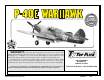
TWO-VIEW DRAWING Use this layout for trim scheme planning only. Not suitable for scale documentation.