
User Manual
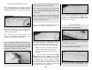

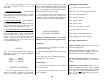


NOTE: If the flexible pipe is bent as
shown in the photo, it will fail after
minimal use. We recommend that you
use the O.S. inside header (OSMG2622).
(*This part was not available when this
photo was taken.)
Here are a few options when using an O.S. 1.20
4-Cycle:
A. Use the stock exhaust system and have it exit
the left side of the cowing.
B. Use the O.S. inside header and flexible
extension (OSMG2682). The flexible extension
can be used with or without the muffler
attached.
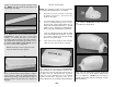
FINAL CONTROL HARDWARE
HOOKUP
❑
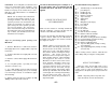
1. Glue the 5/16" x 3/4" x 7/8" hardwood
Flap Servo Mounting Blocks to the die-cut 1/6"
plywood Flap Servo Hatches. Install the flap
servos as shown in the above photo and on the
plans.
❑
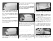
2. Install the flap and aileron horns in line with
the pushrod exits as shown on the plans. Drill
1/16” holes at the proper horn locations, then
saturate the holes with CA glue. Screw the horns
in place with #2 x 3/8” Sheet Metal Screws.
❑
3. Hook up and adjust the aileron and flap
linkages. Two .074 x 4” Threaded End Rods are
provided to make the flap pushrods. The flap
pushrods may be connected to the servos using
Z-bends, or solder-on clevises (not included.)
Refer to the Control Surface Throws section
(page 51) for movement recommendations.
❑
4. The Rudder is hooked up using a Small
Control Horn (cut down to two holes) and a Nylon
Clevis. Refer to the plans for the proper location.
Mark the location of the horn and drill two 1/16”
pilot holes part way through the rudder.
Thoroughly saturate the holes with CA. Put a drop
of CA on the back of the horn and screw the horn
onto the rudder with two #2 x 3/8” Sheet Metal
Screws.
❑
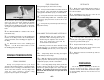
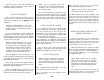
5. The retract switch valve, tank, and servo
installation can be seen in the photo above.
Die-cut parts are supplied to mount the valve. The
tank fits in the built-in cradle in formers F-3 and
F-4, and it can be secured with two #2 x 3/8”
screws and a rubber band (not supplied) or silicone
glue/sealant.
❑
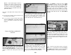
6. Solder-on threaded couplers and nylon
clevises are recommended for internal elevator
and rudder servo hookups. Refer to the photos
and plans for proper servo and horn orientation.
- 50 -