
User Manual


❑
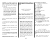
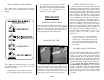
7. The aileron and optional drop tank servo
hook-ups can be seen in the above photo. The
aileron servo uses a Two-ended ball link
connector and Threaded Couplers. You may
want to relieve the notch in W-1 to allow for some
extra clearance. The drop tank release system
uses a quick connector to hook the release cable
to the servo.
❑
8. A throttle linkage is not included, but a
plastic pushrod (GPMQ3714) such as the one
shown in the previous steps works well for most
installations.
COCKPIT FINISHING
(Basic cockpit)
❑
1. Sand the inside of the cockpit around the
edges with 320 grit sandpaper. True up any
uneven edges in the cockpit area.
❑
2. Test fit the pilot into the model. Our Williams
Brothers scale pilot required a 3/8” block under him
to adjust his height. Assemble and paint your pilot.
❑
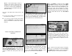
3. You may make a head rest from scrap
balsa like the one shown in the in the photos.
❑
4. Paint the interior of the cockpit. An
alternative to paint is to cover the inside of the
cockpit with a fine grit black sandpaper for a
textured finish. If you use the sandpaper
technique, it is still advisable to paint the cockpit
corners black first.
❑
5. Install the instrument panel decal. It may
be applied directly to the existing panel. Hint: For
best results, stick the decal to a scrap piece of
1/64” to 1/16” plywood, trim it to shape, then glue it
in place.
❑
6. Check the fit of the canopy to the fuselage.
Trim the canopy to the proper line. Glue a strip of
3/32” balsa to the inside of the canopy where
shown. Sand the strip down until it contacts the
fuselage when the remainder of the canopy has a
nice relaxed fit.
❑
7. Paint the frame of the canopy. This can be
done from the inside or the outside; the choice is
yours. The prototype was painted on the outside,
since the glue seems to stick better if the inside is
roughed up with sandpaper and unpainted.
Painting the frame from the outside also allows you
to obtain a flat finish. HINT: “Frisk Film” which is
available at art supply stores is excellent for
masking off the window panes. It can be cut
(carefully) right on the canopy with a sharp #11
blade.
❑
8. Glue the canopy to the model. We
recommend using RC-56 glue or 6-minute Epoxy
to glue on the canopy, but if you have a favorite
technique, use it. You should remove a small strip
of MonoKote (if applicable) from under the frame
for good glue adhesion. Use masking tape to hold
the canopy in place while the glue sets.
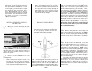
NOTE: The balance and surface throws
for this aircraft have been extensively
tested. We are confident that they
CONTROL SURFACE THROWS:
We recommend the following control surface
throws:
NOTE: Throws are measured at the widest
part of the elevators, rudder, ailerons and
flaps.
ELEVATOR:
(High Rate) 11/16” up 11/16” down
(Low Rate) 9/16” up 9/16” down
RUDDER:
(High Rate) 1-1/2” right 1-1/2” left
(Low Rate) 1-1/4” right 1-1/4” left
AILERONS:
(High Rate) 5/8” up 5/8” down
(Low Rate) 1/2” up 1/2” down
FLAPS:
(Full Down) 1-1/2” down
NOTE: If your radio does not have “dual
rates,” then set up the control surfaces to
move at or slightly less than high rate
throws.
- 51 -