
Manual


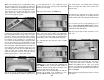


❏❏F2. Install two nylon landing gear straps on
each wire. Use four #2 x 3/8" [9.5mm] sheet metal
screws to hold the straps in place. Note that the
straps are angled so that the screws will fit on the
rails properly. Harden the holes for the screws with
some thin CA.
❏❏F3. Install your wheels on the main landing gear
wires using two 5/32" [4mm] wheel collars and 6-32
x 1/8" [3.2mm] set screws for each wheel. Tighten
the set screws to mark their location on the wires.
Then, remove the wheel collars and wheels. Grind
flat spots on the wires at the marks. Reinstall the
wheels and collars. Use thread locking compound to
secure the set screws.
Use this photo for the next three steps.
❏ F4. Install the tail wheel on the 3/32" [2.4mm] tail
gear wire with two 3/32" [2.4mm] wheel collars and
4-40 x 1/8" [3.2mm] set screws. Grind flat spots on
the wire and use thread locking compound on the set
screws.
❏ F5. Place the rudder over the plan and mark the
location of the tail wheel wire. Note that it is inserted
in the rudder along the centerline of the 1/16"
[1.6mm] ply control horn mount that was inset in the
left side of the rudder. When the control horn is
mounted the screws will go on either side of the wire.
Drill a 3/32" [2.4mm] hole in the rudder for the wire at
the location you marked.
❏ F6. Cut a groove in the LE of the rudder for the tail
gear wire and the nylon hinge. Cut a slot in the rear of
the fuselage for the nylon bearing on the tail gear wire.
Trial fit the rudder to the vertical fin and fuselage with
the tail gear wire installed in the rudder. Do not glue.
Continue with ‘MOUNT THE ENGINE’.
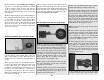
Use this photo for the next four steps.
❏ R13. Install the retract servo in the wing
referring to the plan for the proper location. Cut an
❏❏R9. Lower the landing gear wire a little at a time,
marking and cutting the sheeting to fit the wire.
❏❏R10. Install the wheel on the axle included
with the retract units according to the directions for
the retract units. It is recommended that you use
the 5/32" wheel collars included in the kit, not the
spring clips included with the retract unit. Place the
axle on the gear wire and position the wheel in the
proper location. The wheel should clear the belly
pan by 1/8". Mark the gear wire for the proper
length. Mark the sheeting for the wheel.
Note: The photo at step R7 shows the wire before
it has been cut.
❏❏R11. Cut the gear wire to length at the mark.
Carefully cut the sheeting 1/16" [1.6mm] inside the
marks. Continue trimming the opening to fit the
wheel. Harden the edges of the opening with
some thin CA. Note: The final opening should be
at least 1/16" [1.6mm] oversize.
❏❏R12. With the wheel in the proper location
and the wheel at the correct angle to fit inside the
wing, tighten the mounting screw. Remove the
wheel and axle and grind a flat spot at the mark
made by the screw. Reinstall the axle on the gear
wire and tighten it securely using thread locking
compound on the screw.
❏❏R7. Using the ‘Retract Rail Template’ as a
guide, mark the location of the retract landing gear
on the LE sheeting of the wing. Cut an opening for
the body of the retract gear 1/4" [6.4mm] inside the
marks. Look for the marks you made on the retract
rails when you mounted the retract units earlier. If
you cannot see them, cut another 1/16" [1.6mm]
from the opening. Continue until you can see the
marks. Then, trim the sheeting even with the
marks. Glue the sheeting to the ribs.
Note: If you proceed slowly in the above step and
the steps that follow, you will have neat fitting
openings for your retracts.
❏❏R8. Install the retract unit in the wing with #4
x 1/2" [12.7mm] flat head sheet metal screws (not
included with the model or retract units). Do not
install the wheel until called for.
-40-