DE IN MA A US WARRANTY..... Top Flite Models guarantees this kit to be free of defects in both materials and workmanship at the date of purchase. This warranty does not cover any component parts damaged by use or modification. In no case shall Top Flite’s liability exceed the original cost of the purchased kit. Further, Top Flite reserves the right to change or modify this warranty without notice.
FINISHING ...................................................47 Final Sanding...............................................47 Fuel Proofing ...............................................47 Balance the Airplane Laterally.....................47 Cover the Structure with MonoKote® ...........48 Painting........................................................49 Draw Door and Hatch Outlines....................49 Apply the Decals..........................................49 Cockpit Finishing .....................
PROTECT YOUR MODEL, YOURSELF & OTHERS – FOLLOW THIS IMPORTANT SAFETY PRECAUTION Your Cessna 182 Skylane is not a toy, but rather a sophisticated, working model that functions very much like an actual airplane. Because of its realistic performance, the Skylane, if not assembled and operated correctly, could possibly cause injury to yourself or spectators and damage property.
PRECAUTIONS 1. You must build the plane according to the plans and instructions. Do not alter or modify the model, as doing so may result in an unsafe or unflyable model. In a few cases the plans and instructions may differ slightly from the photos. In those instances you should assume the plans and written instructions are correct. 2. You must take time to build straight, true and strong. 3.
The flaps require one extra channel, a Y-harness, and two standard servos. They are a highly recommended fun option for those who wish to install them. More information on the use of the flaps may be found in the “Flying” section. OPERATIONAL LIGHTING We installed an operational lighting system for added realism and scale appearance. If you plan to use a similar system you should route the wiring before enclosing the wing and fin.
❏ ❏ ❏ ❏ ❏ ❏ ❏ ❏ ❏ ❏ ❏ ❏ Nylon Strapping Tape (required for bending sheeting) Masking Tape (required for construction) Sandpaper (coarse, medium, fine grit)* T-Bar Sanding Block (or similar) Chalk Stick (local drug store) Waxed Paper Thin Cardstock or a File Folder Lightweight Balsa Filler, such as Hobbico HobbyLite™ 1/4-20 and 8-32 Taps and Tap Wrench Isopropyl Rubbing Alcohol (70%) Auto Body Filler (Bondo® or similar) Dremel® Moto-Tool® or similar (optional) *NOTE: On our workbench, we have four 11” T-Ba
CES6F01 CABIN SIDE TOP CES6F02 CES6F03 CES6F04 3/32" X 3" X 18" BALSA HORIZONTAL STAB RIBS “S’s” WINDOW FRAME 3/32" X 3" X 21" BALSA FIREWALL SIDE SUPPORTS NOSE GEAR DOUBLER 1/8" X 6-5/8" X 19" PLY STAB TE STAB TE CES6F05 DIE-CUT PATTERNS 2 REQ. CES6F08 INSTRUMENT PANEL 1 REQ. 1 REQ. 1 REQ. HORN REINFORCEMENT 2 REQ.
AFT FLAP HORN FLAP HATCH CES6W01 AILERON HATCH GUSSETS 1 REQ. OUTER DIHEDRAL BRACE PARTS COWL RING BOTTOM WING JIG PARTS 1/8" X 3-3/4" X 19" PLY CES6W10 1/8" X 3-3/4" X 19" PLY CENTER LE 1/8" X 2-3/4" X 21" BALSA DIHEDRAL STAB CES6W09 GAUGE JOINER (SJ) TOP 1/8" X 2-3/4" X 21" BALSA CENTER AFT SPAR CES6W07 2 REQ. 2 REQ. WING BOLT PLATES FLAP DRILL GUIDE PARTS CES6W08 2 REQ.
Get ready to build 1. Unroll the plan sheets. Re-roll the plans inside-out to make them lie flat. 2. Remove all parts from the box. As you do, figure out the name of each part by comparing it with the plans and the parts list included with this kit. Using a felt tip or ball point pen, lightly write the part name or size on each piece to avoid confusion later. Use the die-cut patterns shown on pages 7 and 8 to identify the die-cut parts and mark them before removing them from the sheet. Save all scraps.
❏ ❏ 7. Pin the left and right S-3 and S-6 ribs to the building board over their locations on the plans. Adjust the height of the Stab TE to align it evenly with the aft edge of the ribs. Glue the ribs to the Stab TE and to the TE Center Brace with thin CA. ribs to the TE. ❏ ❏ 8. Align and glue all of the remaining Stab Lightly sand a bevel along the front edge of the Stab ribs to match the sweep angle of the LE. This will give you a better fit and a stronger glue joint. ❏ ❏ 9.
for misalignment. On a large surface such as the wing, 3/8” extra is suggested. D. To make skins, the following steps are suggested: 1. True up the edges of the sheets with a metal straightedge and a sharp knife or a “T-Bar” sanding block. 2. Test-fit the sheets together to make sure they match well. 3. METHOD “A”: Edge glue the sheets together with thin CA, over a flat surface covered with waxed paper. A quick wipe of the joint with a fresh paper towel will remove excess glue and make sanding easier.
CA to all of the upward facing edges on one side of the stab frame. Place a skin on the frame and hold it in place with your hands until the glue sets. Repeat this for the other bottom skin. Be careful not to bend or twist the stab during this step. ❏ ❏ 2. Use the pattern on the plans to cut four Elevator skins. Sort the skins so that the best surfaces will be facing outward, and on the top. 1/32" ❏ ❏ 3. Cover the elevator plan with waxed paper, then pin a skin in position.
block (the one that will contact the elevator’s LE) to match the angle of the LE. Glue the Torque Rod block in position when you are satisfied with the fit. ❏ ❏ 8. Carefully sand the top of the Torque Rod block flush with the taper of the ribs. ❏ ❏ 9. Mark and sand the inside TE of an elevator skin as you did in step 4. Apply a bead of thick CA to LE, TE, and all ribs, then glue the top skin into position. Hold the assembly flat until the CA cures. ❏ ❏ 10. True up all edges with a T-bar or sanding block.
❏ 18. Tape the Elevators to the Stab making sure that you have the correct clearance around the Balance Tabs. Hold the bent 1/8” Elevator Joiner Wire and Horn up to the Elevator and mark the location of the Joiner Wire holes that will be perpendicular to the hinge line (see the plans for the joiner location). NOTE: The Elevator Horn is off-center. When looking at the top surface of the Stab, the Horn will be to the right of Stab center. ❏ 19. Drill 9/64” holes in the elevators for the Joiner wire.
❏ 11. Remove the fin from the building board and trim off the jig tabs. Blend the LE and TE to the ribs on the right side of the fin. NOTE: If you plan to route wiring for a beacon through the fin, install a 15” length of outer pushrod tube (not supplied) through the 3/16” holes you drilled in step #2. Glue it in position with medium CA, leaving the excess tube protruding from V-1. ❏ 12. Use medium or thick CA to glue on the right side skin. Be sure to get a good bond between the ribs and the skin. ❏ 13.
❏ 8. True up all rudder edges with a sanding block. ❏ 9. Position the rudder against the TE of the fin with the top of the rudder 1/32” above the top of the main body of the fin. Tape the fin and rudder securely together with masking tape. NOTE: Before proceeding, study the photo at step 15 to see what you will accomplish in the next six steps. ❏ 10. Test fit the 3/4” shaped balsa Rudder Tip on top of the rudder. It should butt against the Fin Tip squarely, and have a clearance gap of 1/32” above the fin.
❏ 3. Lay out both sets of balsa Ribs W-2 and W3, ply Doublers W-2B and W-2C, and the ply Wing Bolt Plates exactly as shown in the photo. This way you won’t assemble two right or two left sides. Glue the Doublers to the Ribs and laminate the two pairs of Wing Bolt Plates with 30-Minute Epoxy. After the epoxy has cured, test fit the Wing Bolt Plates into the slots at the aft end of W-2 and W-3.
❏ 12. Check the fit of the 1/4” x 1-7/8” Dowels and the Wing Bolt Plates. Mix up a small batch of 6-Minute Epoxy, then glue these parts in position. NOTE: The Wing Bolt Plates must be flush with the outside surface of the W-3’s. ❏ 13. Trim and sand only the basswood Center Spar ends flush with the W-3’s. Be sure to leave the tips of the Center Aft Spar and the Center LE in place as they will be used when joining the center section to the outer wing panels. WING TE ❏ 14.
❏ ❏ 6. NOTE: Complete this step only if you’re adding operational flaps. Slide two layers of waxed paper between ribs W-6 and W-7 from the TE to just forward of the Aft Inner Spar notch. The waxed paper will help prevent the ribs from sticking together when you cut the Flaps free later on. ❏ ❏ 7. Fit the die-cut 1/8” balsa Aft Inner Spar and Aft Outer Spar into the aft notches of ribs W-4 through W-6 and W-7 through W-14 respectively. The upward facing edge of the Aft Inner Spar protrudes above the ribs.
the rails even if you don’t plan to add flaps, as they add a little extra strength and fill in the notches. ❏ ❏ 15. Glue the 1/8” die-cut Gusset G-3 to the Aft Outer Spar and W-7, as shown on the plans. ❏ ❏ 16. Hold the 36” shaped balsa LE up to the wing and mark it at W-7. Cut three quarters of the way through the LE (from the flat side) with a razor saw to allow it to flex at W-7. Center the LE vertically on the ribs, then tack glue it in position at W-4, W-7 and W-14.
You should now have a right hand and a left hand set of Polyhedral Braces, as shown in the photo. Tracing around the edges of the two shorter parts will help alignment when you glue them together. ❏ ❏ 3. When satisfied that the braces are accurate, use 6-Minute Epoxy to glue the parts together with the alignment marks perfectly aligned. Join the wing panels ❏ ❏ 1.
❏ ❏ 6. Test fit the 1/16” die-cut ply bottom Spar Joiner in the slots. Just like the Polyhedral Braces, the Spar Joiners have one end that is longer than the other. The longer end points towards the wing tip. Equally sand the ends if needed for a good fit between the ribs. Use 6minute or 30-Minute Epoxy to glue the Spar Joiners in position. Clothes pins make handy clamps while the epoxy cures. ❏ ❏ 7. Turn the wing over and repeat the process of installing the Spar Joiners on the top wing spars.
The best balsa filler is no balsa filler! Take your time fitting all sheeting and skins in place. With a little bit of careful sanding you will be rewarded with perfectly matched joints and a lighter, stronger airframe. ❏ ❏ 7. Working quickly, apply a bead of thick CA to the structure that the skin will touch. Don't glue hatch rails yet. Apply glue to the Spar last. Position the skin over the frame, then press it into place.
previous step, or glue two large-diameter pushrod tubes (not supplied) inside the wing, ahead of the spars, to serve as a conduit for the wires. ❏ ❏ 15. Glue the 1/2” x 1/2” x 1” basswood Wing Strut Mount Block to the inboard side of the W-6 rib and to the sheeting at the location shown on the plans. We recommend 6-Minute Epoxy for this job. To help locate the blocks later, drill a 1/16” hole through the center of the blocks, out through the bottom sheeting. ❏ ❏ 16. True all edges with a sanding block.
❏ ❏ 2. Slide the die-cut 1/8” ply LE Jigs over the dowels, with the flat edge towards the sheeted (bottom) side of the wing. the sheeting at the TE of W-3. ❏ ❏ 3. Tack glue the die-cut 1/8” ply TE Jigs to ❏ ❏ 4. Place a die-cut 1/8” plywood Tip Jig under each W-14 rib with the raised tip of the jig butting up to the TE spar. Tack glue it in place.
❏ ❏ 6. Tape the Aileron back into position. Mark the tip end with a straightedge placed along W14. Draw a line 1/16” inboard of the first line. Cut off the Aileron tip on the second (inboard) line. By so doing the Aileron will have 1/32” clearance on both ends when it’s installed. ❏ ❏ 7. Draw a centerline on the LE of the Aileron. Sand a “V” shaped bevel along this edge. Refer to the wing cross section on the plans for the required angle. with its TE aligned with the TE at W-7. ❏ ❏ 8.
BUILD THE FLAPS ❏ ❏ 1. When you look inside the slot that you cut in the sheeting along the Flap LE, you will see two partially die-cut lines on each rib. Insert a pointed piece of wire between the lines, through the top wing sheeting at each end of the flap. We are using a wing section mockup for the purpose of explanation. ❏ ❏ 2. Tur n the wing over, then use a straightedge and hobby knife to cut through the top sheeting, across the two reference marks, along the length of the flap. ❏ ❏ 3.
❏ ❏ 2. Assemble the two Flap Drill Guides (A&B) by gluing the six die-cut 1/8” ply pieces as shown. ❏ ❏ 3. Test fit the flaps. Check that all edges are flush. ❏ ❏ 4. When a good fit is obtained, install large Robart Pivot Point Hinges. NOTE: The hinges are not glued in until after the finish has been applied.
❏ 4. Position (without glue) F-1 through F-9 over the plans and Main Stringer. Are your 3/16” pushrod holes drilled? IMPORTANT NOTE: Cut the “Former Angle” Template from the plans and glue it to stiff cardstock or scrap wood. Trim and sand it to size. Hold it on the AFT side of all formers to position them at the correct angle while gluing. Any small warps or twists will be taken out when the 3/16” stringers are glued in later. ❏ 5.
When everything is locked in place, glue the assembly together. The 3/16” side stringers may now be trimmed flush with the forward edge of F-1. ❏ 12. Lightly sand the outside of the two 36” outer pushrod tubes then insert them through the holes in F-2 through F-8. Trim the tubes so that 1/4” protrudes past F-2 and F-8. Apply a drop of medium CA to the pushrod tubes at each former except F-2. ❏ 13. Use 30-Minute Epoxy to glue the 1/4” birch ply Landing Gear Plate between former LF and F-3.
the Main Stringer. Use Thin CA, wiping up any excess before it dries. Repeat for the other side. These Sub-Stringers will provide a ledge for the side sheeting. ❏ 22. Lightly sand all joints and blend the stringers with the formers in preparation for sheeting. The bottom fuse framework is now ready for sheeting. Sheet the fuselage bottom frame ❏ 1. Remove the Main Landing Gear struts, then pin the fuse framework back on the flat building surface.
❏ ❏ 11. Apply medium CA to all frame parts that the sheet will contact except the top stringer. Roll the sheet into position, starting along the lower edge. Hold it in position by hand and with clothespins until the CA cures. Wick thin CA along the top seam, wiping off the excess before it cures. Repeat Steps 7-11 for the other side of the fuse. ❏ ❏ 12. Cut two 13-1/4” lengths from a 3/32” x 3” x 36” balsa sheet. Hold one of the 13-1/4” sheets in position on the top edge of the Fuse Side from F-3 to F-1.
Remove the hull (I meant to say fuselage) from the building board, and install the landing gear with six 8-32 x 1/2” socket head cap screws. The landing gear struts provide a built-in stand to help avoid hangar rash on the underside.
NOTE: Test fit the entire following assembly (Steps 2-5) before using any glue. ❏ 2. Mix 1/4 oz. of 30-Minute Epoxy. Use epoxy to glue the two die-cut 1/8” ply Firewall Side Supports to F-1 and the Servo Tray. ❏ 3. Use epoxy to glue the Firewall between the two Side Supports and then glue the die-cut 1/8” ply Tank Roof in position. ❏ 4.
❏ 11. Check alignment, then glue the die-cut 1/8” ply Wing Saddle Braces into the notches on F-2B and F-3B. ❏ 12. Fit the die-cut 1/8” ply rear Window Frames into the notches in F-5B and the Wing Saddle Braces. The upper ends should protrude above the Wing Saddle Brace about 3/32”. Glue the Rear Window Frames into position then lightly sand the protruding tips, leaving about 1/16” above the Wing Saddle Brace. balsa Cabin Sides together. ❏ 13. Glue the top and bottom die-cut 3/32” ❏ 14.
its correct length, then insert it from the servo location through F-1 into the Connector on the Nose Wheel Steering Arm. Clip the Metal Clevis onto the servo horn. Align the servo horn and Nose Wheel Steering Arm as shown on the plans. Secure the Pushrod in the Quick Connector with a 4-40 x 1/4” Socket Head Cap Screw. ❏ 6. When the Nose Wheel Steering Arm is adjusted, remove the Nose Gear Wire.
NOTE: Due to the variety of hook-up methods preferred by different modelers, we do not provide any throttle linkage hardware in most of our kits. However, we do offer the following method as one that works well. You probably have the materials buried somewhere under your workbench. ❏ 7. Insert a short length of outer pushrod tube through the throttle hole in the Firewall. Attach a Ball Link to the throttle arm on the engine. Screw a Ball Link Socket onto a 2-56 x 12” threaded wire pushrod.
❏ 3. When the Stab is aligned with the Fuse, draw light reference marks on the Stab to help you accurately reposition it after the glue has been applied. ❏ 4. Apply 30-Minute Epoxy to the Stab Saddle, then lay the Stab in place. Apply a weight to hold the Stab in position until the epoxy cures. Doublecheck alignment before the epoxy kicks off. A ❏ 5. Hold the Fin on top of the Stab with the LE in the notch at the top of F-8B.
❏ 12. Screw a nylon Clevis onto a 2-56 x 4” threaded Pushrod at least 14 revolutions. Slide a Silicone Retainer over the Pushrod, onto the aft end of the Clevis. Clip the Clevis onto the Rudder Torque Rod Horn and center the Torque Rod (i.e., neutral rudder). With the ser vo centered, position the 4” pushrod over the Split Coupling Sleeve, then mark it where it will just miss touching the other pushrod already in the Sleeve. Repeat this procedure for the Elevator. ❏ 13.
❏ 2. Cut 3/16” square balsa Stringers to fit from F-1B to IP. Glue them in position with thin CA. ❏ 3. Use the pattern on the wing plan to cut an Upper Side Panel (not to be confused with Top Panel) from a 3/32” x 2-3/4” x 24” balsa sheet. The curved portion should be sanded for a snug fit under the Stab when the bottom of the sheet is on the Main Sub-stringer. Trim the length to fit flush with the Cabin Side and the aft end of the Stab. The top edge should bisect the stringer.
❏ 11. Sand the shaped 1/4” balsa Dorsal Fillet to blend with the top of the Dorsal Fin and the Fin’s LE. Glue it in place, then sand it to blend with the two Fins. The result should be a smooth, constant radius, without any “bumps” on the ends. ❏ 12. Blend the Dorsal Fin to the Vertical Fin with several thin coats of balsa filler. The object is to have the whole Fin assembly appear as one flowing piece. NOTE: Do not make a fillet where the Fin assembly meets the fuse. ❏ 13.
one end attached to a pin centered at the tail) out to a wing tip. Put a piece of tape on the string to mark the intersection of the string and the wing tip. Swing the string over to the other wing tip and check to see if the distances are the same (see diagram). Adjust the position of the trailing edge of the wing until the wing is properly aligned. NOTE: Make sure the wing is held securely and cannot shift while you are drilling the mounting holes. ❏ 3.
Fin assembly. ❏ 3. Install three hinges in the Rudder and Do steps 4 and 5 after the model is covered. ❏ 4. Pack 30-Minute Epoxy into the tiller hole in the Rudder, then install the Rudder in the same manner as the Elevators. ❏ 5. Hinge the Ailerons using the same technique as the Elevators and Rudder, but without the torque rod insertion steps. THERE SHOULD BE NO HINGE GAP FUSELAGE FINISHING TOUCHES ❏ 1. Bevel the 3/4” x 3” x 6” balsa Lower Aft Fuse Block to fit flush with F-8.
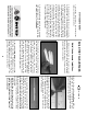
Assemble the cowl ❏ 1. Use a new # 11 blade in a hobby knife to score around the cutlines inside all three parts of the ABS cowl as shown in the photo. Flex the ABS along the scores until the excess material breaks free. Use a Moto-Tool and cutting burr to cut the air intakes and propshaft opening. ❏ 2. Use a sanding block to clean up the edges and to make any adjustments that may be needed for a nice flush fit.
❏ 4. Tape the Cowl on the front of the fuse. Extend the centerlines you drew in step 2 forward to the line on the Cowl. Drill 1/16” pilot holes into the Cowl Mounting Blocks at each intersection. Remove the Cowl and enlarge the holes in only the Cowl to 3/32”. ❏ 5. Install the needle valve. If you will be using a 4-stroke engine, install the choke control wire as well. ❏ 6. Use thin cardstock or a file folder to make location templates as shown in the photo.
❏ ❏ 6. Roughen the mating area of both Wheel Pant halves with coarse sandpaper. Tape the upper half of the Wheel Pant in position, then wick thin CA around the seam. Remove the tape and fill the seam with Bondo®. Sand the Bondo when it has hardened. NOTE: Remove the Landing Gear from the model to do the next several steps. ❏ ❏ 7. Trim the ABS upper and lower Landing Gear Fairings to the cut lines. Cut a slot in both parts to fit at the top and bottom of the Landing Gear as shown.
Install wing struts and fairings NOTE: See the wing plan for a view of the strut ends. ❏ ❏ 1. Poke a T-pin through the hole you drilled in the Wing Strut Mounting block out through the Fuse side. Remember? You glued them behind F-2 at the lower corner of the Fuse. ❏ ❏ 2. Measure and cut two shaped Wing Struts to fit between the pin points and the Strut attachment blocks buried in the wing. Bevel the two ends to fit closely to the Wing and the Fuse. ❏ ❏ 3. Trim the ABS Wing Strut Fairings to the cut lines.
Cover the structure with MonoKote® The Cessna 182 does not require much painting to obtain the scheme shown on the box as most of the finish is done with Top Flite MonoKote. The only painting that is required are the plastic parts such as the cowl, wheel pants, fairings and wing struts. There are many other schemes used on Cessnas but the one shown on the box has proven to be highly visible in the air and is “scale.” The technique we will describe here is the how the model pictured on the box was finished.
We painted all Landing Gear assemblies intact. The wheels were masked off with paper stuffed into the Wheel Pants. By painting the Landing Gear in this manner, all the par ts blended together much better than if we had painted them separately. Painting Paints used on the prototype: We used K&B Super Poxy primer and color coat for all plastic and Butyrate parts. For drawing the door and baggage compartment hatch outlines we used a Staedtler® Lumocolor 313 Permanent fine point pen.
Cockpit finishing ❏ 1. Sand the inside of the cockpit with 320-grit sandpaper. True up any uneven edges in the cockpit area. ❏ 2. Assemble and paint your pilots. We used 1/5 scale Williams Brothers pilots which required a 1” block under them to adjust their height. We glued and screwed our pilots to a piece of 1/8” light ply (not included) which was then screwed to a a couple of blocks glued to the fuse sides. ❏ 3. Paint the interior of the cockpit flat black. be applied directly to the existing panel.
A FEW WORDS ABOUT OPTIONAL LIGHTING Scale lights make a model like this Cessna come to life. We added a rotating beacon, dual landing lights and position lights (see page 5 for part numbers). The rotating beacon is powered by a 9V transistor battery and a miniature circuit board that allows you to vary the “rotation” speed. The beacon and position lights are turned on via a simple toggle switch hidden within the cowling.
❏ 3. We installed a pushrod tube (not included in the kit) along the bottom inside surface of the fuse, to serve as a conduit for the antenna. The antenna was then inserted and pushed to the aft end of the fuse. ❏ 4. The Receiver and Battery may be “wedged” in place under the servo tray with additional layers of foam rubber. ❏ 5.
to slow down for landing. Moving the balance aft makes the model more agile, gives it a lighter “feel” and often improves landing. In any case, please start at the location we recommend and do not at any time balance your model outside the recommended range. ❏ 2. With the wing attached to the fuselage, all parts of the model installed (ready to fly) and an empty fuel tank, suppor t the model at the balance point. ❏ 3. Lift the model at the balance point.
Use a “chicken stick” device or electric starter; follow instructions supplied with the starter or stick. Make certain the glow plug clip or connector is secure so that it will not pop off or fall into the running propeller. Make all engine adjustments from behind the rotating propeller. The engine gets hot! Do not touch it during or directly after operation. Make sure fuel lines are in good condition so fuel will not leak onto a hot engine, causing a fire.
Takeoff If you have dual rates on your transmitter, set the switches to "high rate" for takeoff, especially when taking off in a crosswind. Although this model has good low-speed characteristics, you should always build up as much speed as your runway will permit before lifting off, as this will give you a safety margin in case of a "flame-out." When you first advance the throttle the plane will usually turn left slightly. Correct by applying sufficient right rudder to hold it straight down the runway.
2-VIEW DRAWING Use this layout for trim scheme planning only. Not suitable for scale documentation.