
Owner's manual

NOTE: The 1/8” die-cut plywood formers
are stamped only with the necessary
portion of their name. For example, F-2B is
stamped 2B.
❏ 1. Pin the bottom view of the Fuselage plan
to a flat building surface, then cover it with
waxed paper. Cut the plans apart if necessary.
❏ 2. Use 30-Minute Epoxy to glue the following
1/8” die-cut ply parts together to make sub-
assemblies:
A) Two F-1 formers. Make sure the notches
are aligned.
B) Two F-1B formers.
Don’t glue them to F-1
.
C) Two Fuse Keel parts. Apply weight to hold
them flat.
D) Two FW-A and one FW-B Firewall. Make
sure that FW-B is on the “bottom” of the
stack and that all the tabs are aligned.
E) F2-B and F2-D. F2-D must be glued to the
forward face of F2-B. Make sure that the
dowel holes are aligned.
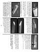
❏ 3. Pin the 3/16” x 3/8” x 48” grooved Main
Stringers to the plans. Be sure that the Main
Stringers are aligned with the outside edge of
the formers and NOT the outside sheeting line
on the plans. When pinning the Main Stringers
at F-1, align them with the dashed line that
extends past F-1. The 1/8” groove faces to
the outside of the fuse. Leave excess material
extending beyond F-1 and at the tail for trimming
to size later.
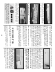
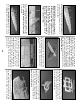
IMPORTANT: Before starting assembly, drill
a 3/16” pushrod hole through each of the
punch-marks on formers F-2 - F-8. All
formers must be installed with the stamped
identification number facing forward. This is
necessary to align the pushrod holes.
Build the fuselage bottom
framework
BUILD THE FUSELAGE
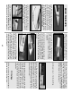
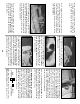
❏❏5. Plug the flaps with the hinges into the
wing. Check the fit and run the flaps through
their complete range of motion. Make any
required adjustments until the flaps swing
freely. Remember, the flaps must close flush
against the wing TE.
❏❏4. When a good fit is obtained, install
large Robart Pivot Point Hinges. NOTE
:
The
hinges are not glued in until after the finish
has been applied. Determine the hinge
locations from the plans (if you forgot to mark
them in the aft inner spar), then drill 3/16”
holes at the hinge locations using the drill
guides to obtain the correct angle for the hinge
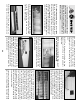
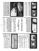
❏❏2. Assemble the two Flap Drill Guides
(A&B) by gluing the six die-cut 1/8” ply pieces
as shown.
❏❏3. Test fit the flaps. Check that all edges
are flush.
28