
Owner's manual

❏ 4. Position (without glue) F-1 through F-9 over
the plans and Main Stringer.
Are your 3/16”
pushrod holes drilled?
IMPORTANT NOTE: Cut the “Former Angle”
Template from the plans and glue it to stiff
cardstock or scrap wood. Trim and sand it
to size. Hold it on the AFT side of all
formers to position them at the correct
angle while gluing. Any small warps or
twists will be taken out when the 3/16”
stringers are glued in later.
❏ 5. Using the Former Angle template, start
gluing the formers to the Main Stringers starting
with F-3, working towards the rear. Don’t glue
F-1 or F-2 yet.
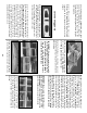
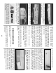
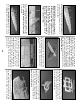
❏ 6. Insert (without gluing) two 3/16” x 3/16” x
48” stringers into the lowest notches on both
sides, that run from F-1 to F-9 as shown in the
photograph. Starting at F-9, check the former
angle once again with the Former Angle
template. Make sure that you straighten out any
twists, then glue the stringers to F-9 with thin
CA. Continue forward, checking and aligning
each former before reaching for the CA. F-3 is
the last former you need to glue to the
stringers at this time.
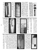
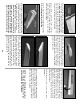
❏ 7. Insert and glue the 1/8” die-cut former LF
into the slot in the fuse Keel. Make sure that it is
square and flush with the top and bottom of
the Keel.
❏ 8. Insert the Keel assembly into the upper
center notches of F-2 and F-3. The notches on
the tips of LF should be resting on the 3/16”
stringers. Adjust F-2 so that the bottom ends are
over the dashed reference lines on the plan and
the forward edge of the Keel is flush with the aft
side of F-2. Glue F-2, the Keel and LF at all
points of contact.
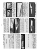
❏ 9. Glue the two halves of the die-cut 1/8” ply
Servo Tray together. Cut four 1/8” x 1/4” x 2-1/4”
doubler strips from scrap ply left over from die-
cut sheets. Glue these doublers on both ends of
the servo holes for reinforcement.
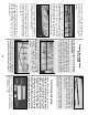
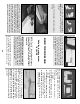
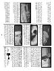
❏ 10. Carefully lift F-1 out of the frame.
You
didn’t glue it in, did you?
Insert the forward end
of the Servo Tray into the Firewall opening in F-
1. The servo reinforcement strips should face
away from the building board.
❏ 11. Fit F-1 and the Servo Tray back into the
fuse frame. Work the aft end of the Servo Tray
into the notch in F-2. Align F-1 over the plan.
29