
Owner's manual

A FEW WORDS ABOUT
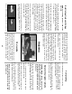
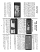
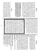
OPTIONAL LIGHTING
Scale lights make a model like this Cessna come
to life. We added a rotating beacon, dual landing
lights and position lights (see page 5 for part
numbers). The rotating beacon is powered by a 9V
transistor battery and a miniature circuit board that
allows you to vary the “rotation” speed. The beacon
and position lights are turned on via a simple
toggle switch hidden within the cowling. The
landing lights are powered directly from the flight-
pack battery and are plugged into the receiver. By
activating a sixth channel, we can turn the lights on
and off from the transmitter. You could also “Y” the
landing lights into the throttle or flap servo so when
either is operated, the lights would come on.
Pockets built-in to the cowl greatly simplify
the installation of landing lights. The wiring was
modified to include a “Deans” connector and a
firewall-mounted plug so the cowling can be
removed without having to cut the wires.
The circuit boards and 9V battery were
wrapped in foam rubber and installed under the
servo tray along with other electronic components.
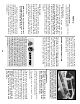
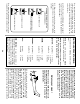
❏ 1. Epoxy the 5/16” x 3/4” x 7/8” hardwood
Servo Mounting Blocks to the die-cut 1/16” ply
Flap and Aileron Servo Hatches. Install the
Flap and Aileron servos as shown in the photo
and on the plans.
After “fishing”
the servo wires
through to the opening at the center of the wing,
plug them into a “Y” harness. Before
permanently screwing the servo hatches in
position, hook up your radio and set
centering
and
direction
of both sets of servos.
❏ 2. Drill 3/32” holes through the Servo Hatches
at each of the six punch marks. Position the
hatches in their respective openings, then drill
1/16” pilot holes into the hatch support rails.
Use #2 x 3/8” flat head sheet metal screws to
install the servo hatches.
❏ 3. Install the Aileron Horns in line with the
pushrod exits as shown on the plans. Drill 1/16”
holes into the Ailerons at the proper horn
locations. Screw the horns in place with #2 x
3/8” sheet metal screws.
NOTE: Put a couple of drops of thin CA
into each screw hole before reattaching
the horns.
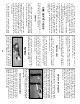
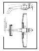
❏ 3. Four .074 x 4” Threaded End Rods are
supplied to make the Flap and Aileron
pushrods. Screw a nylon Clevis and silicone
Retainer on each pushrod. The Flap pushrods
are connected to the servos using nylon
Faslinks
™
as shown in the photo. Aileron
pushrods are attached to the servos with solder
clevises. Hook up and adjust the Aileron and
Flap linkages. Refer to the Control Surface
Throws section for movement recommendations.
❏ 4. Permanently install the Elevator (as
described on page 42 in Steps 3 & 4) and the
Rudder (page 43, Steps 4 & 5).
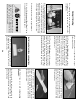
❏ 1. Wrap the Receiver and Battery in 1/2” foam
rubber (Hobbico HCAQ1050) securing the foam
with rubber bands.
❏ 2. Protect both components from fuel leakage
by sealing them in plastic wrap or plastic bags.
Seal the plastic closed with masking tape.
Install receiver, battery and antenna
Flap/aileron control hookup
FINAL HOOKUPS
AND CHECKS
51