
User's Manual


4
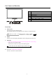
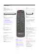
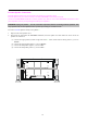
Part Names and Function
1. POWER
2. POWER/Standby Indicator
3. REMOTE SENSOR Windows
4. INPUT Select
5. MENU
6. SETTING
7. ADJ. + , ADJ. - / VOL + , VOL -
8. CH+, CH-
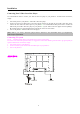
Front View
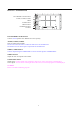
4. INPUT Select
Switch the input in the following order.
The available component input depends on the setting of “component input”.
Video Æ S-video Æ Component input ( YCbCr or YPbPr )
TV Å DVI Å D-sub 15 PIN
5. MENU
Sets the On-Screen Display (OSD) Menu mode and displays the main menu.
6. SETTING
. In the on screen menu execute the selected highlight item or level setting
˙ Not in the on screen menu mode:
Switches the second screen input in the following order
Video Æ S-video Æ Component input (YCbCr) ÆTV
8. CH
+, CH- (Only for TV function)
Increase / decrease TV channel number.
CH
8 7 6 5 4 3
2
1