/ SEIKAKU TECHNICAL GROUP LIMITED NF03473 -RS Series A5 , MAXX PACKGE SERIES TOPP PRO_V1.2 TPS A4 NH00149 5:2 A3 PHFUA102-20100900001 , 2011.05.23 20 . 1.1 2013.01.30 :QHFBE004-20130100013 1 1.2 NO 2 10 JAN.30.
MAXX SER IES USER' S MANUAL MAXX i8HA-222PACK NF03473-1.
MAXX * MAXX8A SUB is Active Subwoofer for professional use, It can be used in following electromagnetic environment: residential, commercial and light industrial, urban outdoors. It is the apparatus Not intended for rack mounting. * The maximum length of cables: Audio input less than 10m * For MAXX8A SUB, the peak inrush current is 3.
MAXX TABLE OF CONTENTS 1. INTRODUCTION ...............................................................................1 2. FEATURES .......................................................................................1 3. USEFUL DATA ...................................................................................1 4. REAR PANEL DESCRIPTION.................................................................2 5. CONNECTION PLATE .........................................................................3 6.
MAXX INTRODUCTION Thank you for choosing TOPP PRO products. Our professional Audio Products are designed and tested by a highly qualified engineering team with more than 30 years of experience. Great pride & care are placed in delivering the products with excellent performance, specifications and dependable reliability. Also great emphasis is placed in creating and bringing to market products that can fill multiple applications and also offer customer exceptional value.
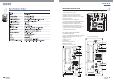
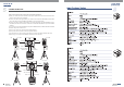
MAXX REAR PANEL DESCRIPTION ACTIVE SUBWOOFER MAXX 10A/12A/15A SUB (9)(10)(11)(12) (13) (6) 110 -120V (7) 220 -240V ON LEFT / MONO - RIGHT IN SIGNAL LIMIT (8) LEFT / MONO MAX VOLUME 8 (1)ON-OFF main power switch (2)Input AC power socket with main fuse (3)POWER, Green LED, indicate ON status (4)BYPASS Switch Select High pass filter or bypass (5)Ground Lift Switch (6)LINE IN RIGHT.
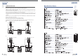
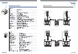
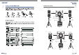
MAXX 5 CONNECTION PLATE Two Active Subwoofers & Two Active Satellite Speakers 1)Make your initial connections with all the equipment powered off, and ensure that all the main volume controls are turned completely. 2)Connect one side of the signal cable at your audio mixer into OUTPUT LEFT/RIGHT, and the other side of the cable into the LINE INPUT of your active subwoofers.
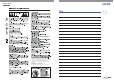
MAXX 5 CONNECTION PLATE (C) LINE IN LINE IN TPS i28HA Pole TPS i28HA Pole MAIN OUT LEFT MAIN OUT RIGHT LINE IN LEFT/MONO LINE IN LEFT/MONO USB PLAYER 00 MP3 USB REP 03 :08 ALL TAC-MP3-T POWER (Push & Hold) POWER PHANTOM 48V INTERNAL EFFECTS REV + VIBRATO WARM HALL REV + CHORUS GAIN GAIN 75Hz 75Hz LINE MP3 75Hz BRIGHT ROOM 13 WARM VOCAL 12 BRIGHT VOCAL 1 9 8 2 3 4 5 11 CHORUS PLATE REVERB MONO DELAY STEREO DELAY FX INPUT LEVEL 16 14 WARM ROOM VIBRATO FLANGER REV
MAXX 5 CONNECTION PLATE One Active Subwoofer & Two Active Satellite Speakers 1)Make your initial connections with all the equipment powered off, and ensure that all the main volume controls are turned completely. 2)Connect one side of the signal cable at your audio mixer into OUTPUT LEFT/RIGHT, and the other side of the cable into the LINE INPUT LEFT/RIGHT of your active subwoofer.
MAXX 5 CONNECTION PLATE (C) TPS i28HA TPS i28HA LINE IN LINE IN MAXX 12A SUB LINE IN LEFT/MONO Tripod Mount LINE IN RIGHT MAIN OUT LEFT Tripod Mount MAIN OUT RIGHT USB PLAYER 00 MP3 USB REP 03 :08 ALL TAC-MP3-T POWER (Push & Hold) POWER PHANTOM 48V INTERNAL EFFECTS REV + VIBRATO GAIN GAIN GAIN 75Hz GAIN 75Hz 75Hz 75Hz WARM HALL 15 REV + FLANGER BRIGHT HALL REV + CHORUS WARM ROOM BRIGHT ROOM 13 VIBRATO WARM VOCAL 12 FLANGER BRIGHT VOCAL 1 9 8 2 3 4 5 11 CHORUS
MAXX 6 FREQUENCY RESPONSE DIAGRAM MAXX 10A SUB +110 T TT TTTTT T TTTT +100 d B S P L +90 +80 +70 +60 20 50 100 200 500 1k 2k 5k 10k 20k Hz MAXX 12A SUB +110 T TT TTTTT T TTTT +100 d B S P L +90 +80 +70 +60 20 50 100 200 500 1k 2k 5k 10k 20k Hz MAXX 15A SUB +110 T TT TTTTT T TTTT +100 d B S P L +90 +80 +70 +60 20 50 100 200 500 1k Hz 7 2k 5k 10k 20k
MAXX 6 FREQUENCY RESPONSE DIAGRAM TPS i8HA +110 TTT TT +100 d B +90 S P L +80 +70 +60 20 50 100 200 500 1k 2k 5k 10k 20k Hz TPS i10HA +110 T TT TTTTT T TTTT +100 d B S P L +90 +80 +70 +60 20 50 100 200 500 1k 2k 5k 10k 20k Hz 8
MAXX 6 FREQUENCY RESPONSE DIAGRAM TPS i12HA +110 TTT TT +100 d B S P L +90 +80 +70 +60 20 50 100 200 500 1k 2k 5k 10k 20k Hz USB PLAYER 00 MP3 USB REP 03 :08 ALL TAC-MP3-T POWER (Push & Hold) POWER PHANTOM 48V INTERNAL EFFECTS REV + VIBRATO WARM HALL REV + FLANGER BRIGHT HALL REV + CHORUS WARM ROOM GAIN GAIN 75Hz GAIN 75Hz 75Hz LINE MP3 75Hz 15 13 WARM VOCAL 12 BRIGHT VOCAL 1 9 8 2 3 4 5 11 CHORUS PLATE REVERB MONO DELAY STEREO DELAY FX INPUT LEVEL 16
MAXX WIRE CONNECTIONS Either the 1/4" TRS phone jack or XLR connector can be wired in balanced and unbalanced modes, which will be determined by the actual application status, please wire your system as the following wiring examples: For 1/4" Phone jack + - + Tip + Tip Ring Tip Ring Sleeve Sleeve Sleeve TRS Type Balanced TS Type Unbalanced TRS Type Unbalanced For XLR Connector Pin2 (+) Pin3 (-) (Linked to Pin1 manually, Pin2 (+) Pin3 (-) ) Pin1 ( ) Pin1 ( ) XLR Type Unbalanced XLR Type
MAXX 8 TECHNICAL SPECIFICATIONS MAXX 10A SUB 325 465 421mm (12.80" 18.31" 16.
MAXX TECHNICAL SPECIFICATIONS MAXX 15A SUB 8 124.
MAXX 8 TECHNICAL SPECIFICATIONS TPS i10HA TPS i28HA 13
MAXX TECHNICAL SPECIFICATIONS TPS i12HA 8 14
MAXX 9 GUARANTEE Topp Pro guarantees the normal operation of the product against any defect of manufacture and/or vice of material, by the term of (12) months, counted as of the date of purchase on the part of the user, committing itself to repair or to change, to its election, without position some, any piece or component that will fail in normal conditions of use within the mentioned period.
Note
MAXX