
User Manual

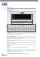

1). Assign of input and output channels
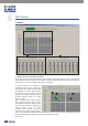
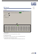
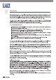
In this area, there are many small blocks, click one block, its background turns green, audio signal
flow from left input channel to top output channel; while the signal won’t go through any
channel if it is not active. Below figure gives an example:
a. Click the block as a marked, its
background turns green, means that
signal input from channel Local 02 will
be assigned to output channel Local
02. But the input channel Local 02
wouldn’t be assigned to other output
channels because there is no other
block activates.
b&c. Click the block as b&c marked,
their background turn green, means
that signal input from channel Local
03 and Local 04 will be assigned to
output channel Local 03. Other
channels that inactive won’t be
assigned to any other output channel.
d&e. Click the block as d&e marked, their background turn green, means corresponding input
channel signal will be assigned to corresponding output channel.
And so on...
1
2 3
a
b
c
e
d
4. MATRIX
14
DSP Control
6