
User Manual

6
SYSTEM AIR PURGE PROCEDURE DESCRIPTION
IMPORTANT: BEFORE FIRST USE,
perform the following Air Purge Procedure to remove any air
that may have been introduced into the hydraulic system as
a result of product shipment and handling. This step is to be
completed without and weight on the jack.
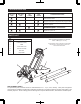
Model T815016LT features a 3,000- lb. maximum capacity.
The jack features an overlad valve bypass system to
prevent jack damage and user injury.
Maximum Load Capacity........................1½ tons (3,000-lb.)
Minimum Lifting Height............................................3½ inch
Maximum Lifting Height.........................................14⅛ inch
WARNING: This Product contains chemicals known to
the state of California to cause cancer and birth defects or
other reproductive harm.
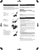
OPERATION
Raising the Jack
1. Block the vehicle’s wheels for lifting stability.
2. Set the Parking Brake in the vehicle.
3. Close the release valve by turning the handle clockwise
as far as it will go.
4. Refer to the vehicle manufacturer owner’s manual to
locate approved lifting points on the vehicle. Position the
jack so that the saddle is centered and will contact the
5. Before raising the vehicle double check and verify the
saddle is centerd and also has full contact with the lifting
point.
6. Continue to pump the jack handle to lift the vehicle to the
desired height. After lifting, support the load with
appropriately rated vehicle support stands before
working on the vehicle.
Lowering the Jack
1. Raise the load.
2. Remove support stands.
3.
on to the jack handle so your hands do not slip and
ensure the release valve does not rapidly lower.
4. Carefully open the Release Valve by slowly turning the
handle counterclockwise. (Do not allow bystanders
around the jack or under the load when lowering the
jack.)
WARNING The jack handle may turn rapidly.
Use extreme caution when lowering the jack; this can
cause the release valve to lower rapidly. Failure to head
these warnings could cause serious injury or death.
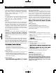
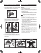
STEP 1:
Turn release valve
counterclockwise on
full turn to the open
position.
STEP 2:
Pump handle eight
full strokes rapidly..
STEP 3:
Carefully and slowly
to release trapped air.
STEP 4:
Turn release valve clockwise
to the closed position and
check for proper pump action.
It may be neccesary to
perform the above step
more than once to assume
air is evacuated totally.
Counterclockwise
rotation
Up and down
reciprocating motion
With tool pinch oil fill plug
Clockwise rotation