
Operator's Manual


g026924
1
2
3
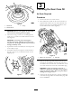
Figure2
1.Wheelhub
3.O–ring
2.Wheelhubnut
Important:Donotover–tightenthewheelhub
nutbecausethebearingwillwearrapidly.
2.ChecktheO–ringtoassureitisnotdamaged,and
makesureitisseatedintheinsidediameterofwheel
hub(Figure2).
Important:AnO–ringthatisdamagedor
installedincorrectlywillallowoiltoleakoutof
thegearcase.Ifenoughoilleaksout,mechanical
damagewilllikelyresult.
3.Ifpneumaticwheelsareinstalled,setthetirepressure
at241.3Kpa(35psi).
4.Installdrivewheelswithcapscrewsandlockwashers
(Figure3).Donottrytoinstallthewheelsoverthe
shippingcaps
g026925
Figure3
3
CheckingtheGearCaseOil
NoPartsRequired
Procedure
1.Positionthemoweronalevelsurface.
2.Raiseandblockthebackofthemoweruntilthereis
approximately0.260m(10–1/4inches)betweenthe
bottomofthegearcaseextendingbehindtheroller
bracketandthelevelsurface(Figure4).
g026926
2
1
Figure4
1.0.260m(10–1/4inches)
2.Fillerplug
3.Removethellerplugfrominsideofeachthegear
case(Figure4).Checktheoillevelinthegearcase:it
shouldbelevelwiththebottomofthellerhole.Ifthe
oilislevelwithbottomofthehole,reinstallllerplug.
Important:Checkforoilleakscausedbya
defectiveorimproperlyinstalledO–ringorgasket,
andloosesideplatebolts.Makeallrepairsbefore
addingoiltothegearcases.
4.Iflevelofoilislow,llgearcasetopointofoverowing
withSAE80–90gearlubeandreinstallllerplug.DO
NOTOVERFILL.
5