
Operator's Manual


BACKLAPPING THE CUTTING
UNITS
The cutting units may be backlapped on the machine.
Backlap Kit, Part no. 84-5510 is available from your
Authorized TORO Distributor.
Backlap according to procedures in the Toro Sharpening
Reel and Rotary Mowers Manual Form No. 80-300 PT.
SETTING HEIGHT OF CUT AND
LEVELING THE REAR ROLLER
(Floating Cutting Units)
Note: For best results, perform adjustments on the
cutting units when they are removed from traction unit.
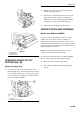
1. Position the cutting unit on a flat level table or
board.
2. Slightly loosen the nut securing each roller bracket
to the angle bracket.
3. Adjust the support capscrew to achieve 25 mm ±2
mm dimension between the height-of-cut support
and the front roller bracket (2 places).
4. Adjust the support capscrew to achieve 16 mm +2
mm dimension between the height-of-cut support
and the rear roller bracket (2 places).
5. Remove the hairpin cotters securing the rear height-
of-cut pins and install them in the 1/2" setting as
shown on the height-of-cut plate.
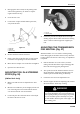
Figure 43
1. Roller bracket
2. Angle bracket
3. Height-of-cut pin
4. Support capscrew
5. Locknuts
6. Remove the hairpin cotters securing the front
height-of-cut pins and install them in the 6 mm
setting as shown on height-of-cut plate to allow
clearance between the roller and table.
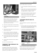
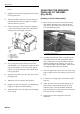
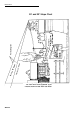
7. Position a 2 cm or thicker bar under the reel blades
and against the front face of the bedknife. Make
sure the bar covers the full length of the reel blades.
8. Check that the rear roller is level by inserting a
piece of paper under each end of the roller.
9. Level the roller by adjusting the appropriate support
capscrew on the rear roller supports until the roller
is parallel and the entire length of the roller touches
the table.
10. When the roller is level, adjust both rollers to the
desired height-of-cut pins. Tighten the nuts securing
the roller brackets.
11. Verify that the rollers are level and the bedknife is
parallel to the surface.
(Fixed Cutting Units)
Note: For best results, perform adjustments to the
cutting units when they are mounted on the traction unit.
1. Position the cutting unit on flat level surface or
Maintenance
31
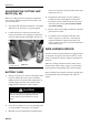
Be careful when lapping the reel because contact
with the reel or other moving parts can result in
personal injury.
CAUTION
Under no circumstances use a short-handled
paintbrush. A Part #29-9100 handle assembly
complete—or individual parts—are available from
your local Authorized TORO Distributor.
DANGER
4
1
2
5
16 mm
3
2.5 cm