
Operator's Manual


Setup
1
AssemblingtheHandle
NoPartsRequired
Procedure
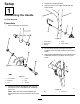
1.Slide2bushingsintotheframe.
g017333
1
2
3
4
5
6
g017333
Figure3
1.Lowerhandle4.Frame
2.Bushings5.Bolt
3.Nut6.Washers
2.Placethelowerhandlebetweenthebushings
andsecureitwith1handlebarbolt,2washers,
and1nut.
Note:Placethelowerhandlebetweenthe
bushingswiththekickstopassemblyattheright
side.
3.Repeatfortheoppositeside.
4.Aligntheholesontheupperhandlewiththe
lowerhandle.
g209291
Figure4
1.Upperhandle4.U-bolt
2.Handwheel5.Lowerhandle
3.Washer
5.FittheU-boltthroughtheupperandlower
handleandsecureitwithawasherandahand
wheel.
6.Attachthethrottleassemblytotheoutsideofthe
handlebarandsecureitwithanutandapan
screw.
g209280
Figure5
1.Nut2.Panscrew
6