
Operator's Manual
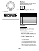
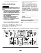

ttedsothatthebentsectionofthetubeangles
towardtheground.
g281281
Figure3
Leftsideshown
1.Cap
4.Lowerhandlebar
2.Hexlocknut5.Removethehexnutand
installthelowerhandlebar
here.
3.Clampplate
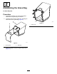
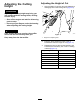
3.Installthebottomofthebracehandlebarsto
eachsideofthemowerdeckusingabolt,at
washersontheinsideandoutsideofthedeck,
andalocknut(Figure4).
g281383
Figure4
Leftsideshown
1.Hexlocknut3.Bracehandlebar
2.Flatwasher4.Bolt
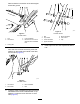
4.Installtheupperhandlebarsandtopofthebrace
handlebarstothelowerhandlebarswith3cup
washers,2boltsand2hexlocknutsoneach
side(Figure5).
g281404
Figure5
Leftsideshown
1.Bolt5.Bracehandlebar
2.Cupwasher
6.Hexlocknut
3.Lowerhandlebar
7.Cap
4.Upperhandlebar
5.Installcapsoveralloftheexposedhandlebar
nuts.
5