
Operator's Manual


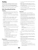


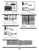

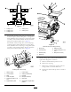

Figure2
1.Cuttingunit14.Cuttingunit4
2.Cuttingunit25.Cuttingunit5
3.Cuttingunit3
6.For254mm(10inch)cuttingunits,tthebumpstop,
2roller-boxplates,andtherollerplatetocuttingunits1
and5(hydraulic-motorend)using1carriagebolt(M10
x55mm),1hex-headbolt(M10x90mm),2locknuts
(M10),and2washers(M10);refertoFigure3.
For200mm(8inch)cuttingunits,tthebumpstop,
1roller-boxplate,andtherollerboxtocuttingunits1
and5(hydraulic-motorend)using1carriagebolt(M10
x55mm),1hex-headbolt(M10x90mm),2locknuts
(M10),and2washers(M10);refertoFigure4.
Figure3
Cuttingunits1and5only
1.Washer(M10)7.Locknut(M5)
2.Locknut(M10)8.Cutting-unitassembly
3.Plate9.Forward
4.Roller-boxplate
10.Bolt(M10x90mm)
5.Carriagebolt(M10x55
mm)
11.Bumpstop
6.Rightdeectorplate
12.Handwheelinangled-back
position
Figure4
200mm(8inch)cuttingunitonly
1.Bumpstop5.Roller-boxplate
2.Locknut(M10)6.Carriagebolt(M10x55
mm)
3.Washer(M10)7.Bolt(M10x90mm)
4.Rollerbox
7.Modifycuttingunits4and5fromleft-handto
right-handcongurationasfollows:
A.Removeanddiscardtheprotectivecover.
B.Removethesnapring.
C.Removethecounterweighttogetherwiththe
O-ringandtittothenon-driveend.
D.Tightenthesocket-headcapscrewsto80N-m
(59ft-lb).
10