
Setup Instructions


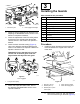


5.Removethewheels(Figure1).
6.RemovethedeckcoverandthePTO
engagementlinkagerodbeforeliftingand
movingtherotarycuttingdeckintoposition
againstthepowerunit(Figure2).
g237246
Figure2
1.Liftpoints
Note:Retainallremovedpartsforlater
installation.
2
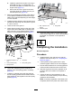
InstallingtheCuttingDeck
Partsneededforthisprocedure:
8
Bolt(3/8x1inch)
8
Curvedwasher
8
Flangenut(3/8inch)
Procedure
1.Install8bolts(3/8x1inch),curvedwashers,
andangenutstosecuretherotarycuttingdeck
tothepowerunitasshowninFigure3.
Important:Ensurethattheenginedeckis
paralleltothemowerdeck+/-0.5degrees
beforetighteningthexingbolts.
g237289
Figure3
1.Bolt(3/8x1inch)3.Curvedwasher
2.Flangenut(3/8inch)
4.Reversedhardware
Note:Installtheboltsandwasherstogether
onthesamesideoftheframe.Thereversed
hardwareinstallswiththeboltendandnutfacing
outwards.
2.Torquetheboltsto40to47N·m.
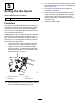
3.ScrewthePTOengagementlinkagerodintothe
powerunitbell-crankyokeandthenconnectthe
otherendtotheassistarmandsecureitwiththe
hairpincotter(Figure4).
2