
Setup Instructions


B.Installtheguardtothetractionunitusing2
bolts(M8x25mm),4washers(M8–17),
and2locknuts(M8)inthelowerholeonthe
engineframe(Figure6).
C.Securethefrontoftheguardtothedeck
usingthecenterbolt,washer,andnutyou
removedpreviously(Figure6).
2.RefertotheAdjustingtheHeightofCutsection
intheOperator'sManualandchecktheheight
settingoftherearaxledependingonwhatheight
ofcutisrequired.
3.Installthetractionwheelstothehubsandsecure
withthedrivewheellugnuts;torquethelugnuts
to122to129N·m.
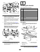
4.Lowertheunittotheground.
5.Centerthedrivepulleyguardontherearofthe
engineframeandinstallitwith2carriagebolts
(M10x25mm),heavywashers(M10),spring
washers,andnuts(M10)asshowninFigure7.
g237375
Figure7
1.Carriagebolt(M10x25
mm)
4.Nut(M10)
2.Heavywasher(M10)
5.Drivepulleyguard
3.Springwasher
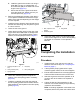
6.Testttheundersideguardandadjustthe
positionofthedrivepulleyguardifnecessary
(Figure8).
7.Installtheundersideguardanddragshieldto
thedrivepulleyguardandsecurethemwiththe
boltscapturedinthelanyardsonthedrivepulley
guard(Figure8).
g237378
Figure8
1.Bolt,capturedinthe
lanyard
3.Dragshield
2.Undersideguard
8.Adjustthecasterpositionandthebladeheight
tothecorrectheightofcut;refertotheAdjusting
theHeightofCutsectionintheOperator’s
Manual.
4
CompletingtheInstallation
NoPartsRequired
Procedure
1.Installthedeckcoverandsecureitwiththe
fastenersremovedinstep6of1Preparingthe
Machine(page1).
2.Ifthehydraulicpumpbypassvalveisopen,
closethebypassvalves,butdonotovertighten.
3.Ensurethatallfastenersarecorrectlytightened
andthatalluidlevelsareatthecorrectlevel.
4.Starttheengineandchecktheoperationofall
controls;refertothetractionunitOperator’s
Manual.
5.Collectallpartsanddocumentationforthe
customer.Filloutthewarrantyandpre-delivery
inspectiondocumentation.
Note:Awarrantyregistrationcardneedstobe
completed,bothforthepowerunitandthedeck.
4