
Setup Instructions
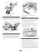
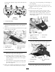
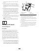

Figure1
3.RemovethedeckcoverandthePTOengagement
linkagerodbeforeliftingandmanoeuvringtherotary
cuttingdeckintopositionagainstthepowerunit
(
Figure2).
Figure2
1.Liftpoints
4.Install8bolts(3/8x1inch),curvedwashers,and
angenutstosecuretherotarycuttingdecktothe
powerunit.NotetheboltorientationinFigure3.
Ensurethattheenginedeckisparalleltothemower
deck+/-0.5degreesbeforetighteningthexing
bolts.
Figure3
1.Flangenut(3/8inch)3.Bolt(3/8x1inch)
2.Curvedwasher
Note:Figure3showsthefastenersoutsideofthe
mowingunittobetterillustratewhichconguration
goeswitheachhole.Installtheboltsandwashers
togetheronthesamesideoftheframe.
5.Torquetheboltsto40to47N-m.
6.ScrewthePTOengagementlinkagerodintothe
powerunitbell-crankyokeandthenconnectthe
otherendtotheassistarmandsecureitwiththe
hairpincotter(
Figure4).
Figure4
7.AdjustthePTOengagementasdirectedinthe
AdjustingthePTOEngagementLinkagesectionin
thetractionunitOperator’sManual.
8.ChecktheadjustmentofthePTOSafetySwitchas
directedintheAdjustingthePTOSafetySwitch
sectionofthetractionunitOperator’sManual.
9.Checkthedeckdrivebeltrouting(Figure5).Refer
totheAdjustingtheMowerBeltTensionsection
intheOperator’sManualtocorrectlyadjustthedeck
drivebelt.Ensurethebeltisonthecorrectsideof
2