
Setup Instructions

thebeltguideundertheengineframeandadjustthe
beltguide.
g015218
1
1
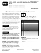
Figure5
PTOengaged
1.Toenginedrivepulley
10.Checkandadjustthebladebrake;refertothe
AdjustingtheBladeBrakesectionoftheOperator’s
Manual.
11.Installthecenterdischargeguardbetweentheengine
frameandthecutterdeck.
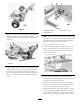
Figure6
1.Bolt(M8x25mm)4.Centerboltandwasher
2.Washer(M8–17)5.Washer(M8–17)and
locknut(M8)
3.Centerdischargeguard
A.Removethecenternut,boltandwashersfrom
thecenterxingonthedeck(Figure6).
B.Installtheguardtothetractionunitusing2
bolts(M8x25mm),4washers(M8–17),and2
locknuts(M8)inthelowerholeontheengine
frame(Figure6).
C.Securethefrontoftheguardtothedeckusing
thecenterbolt,washer,andnutyouremoved
previously(
Figure6).
12.RefertotheAdjustingtheHeightofCutsectionin
theOperator'sManualandcheck/adjusttheheight
settingoftherearaxledependingonwhatheightof
cutisrequired.
13.Installthetractionwheelstothehubsandsecure
withdrivewheellugnuts.TorqueNutsto122-129
N-m.
14.Lowertheunittotheground.
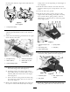
15.Installthedrivepulleyguardtotherearofthe
engineframewith2carriagebolts(M10x25mm),
heavywashers(M10),springwashers,andnuts
(M10)(
Figure7).Ensurethatyoucentertheguard
ontheengineframe.
1 2 3 4
5
G018373
Figure7
1.Carriagebolt(M10x25
mm)
4.Springwasher
2.Drivepulleyguard
5.Nut(M10)
3.Heavywasher(M10)
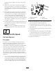
16.Testttheundersideguardandadjusttheposition
ofthedrivepulleyguardifnecessary(Figure8).
Figure8
1.Undersideguard3.Bolt,capturedinthe
lanyard
2.Dragshield
17.Installtheundersideguardanddragshieldtothe
drivepulleyguardandsecurethemwiththebolts
3