
Setup Instructions
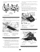

capturedinthelanyardsonthedrivepulleyguard
(Figure8).
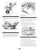
18.Adjustthecasterpositionandthebladeheightto
thecorrectheightofcutreferringtotheAdjusting
theHeightofCutsectionintheOperator’sManual.
Installthedeckcoverandsecureitwiththeremoved
fasteners.
19.Ifthehydraulicpumpby-passvalvewasopenedso
thepowerunitcouldbepushed,closetheby-pass
valves,butdonotovertighten.Checkallfasteners
arecorrectlytightenedandalluidlevelsareat
thecorrectlevel.Starttheenginereferringtothe
StartingandStoppingsectionintheOperator’sManual
andchecktheoperationofallcontrols,referringto
theOperator’sManual.
20.Collectallpartsanddocumentationbacktogetherfor
thecustomer.Filloutthewarrantyandpre-delivery
inspectiondocumentation.
Note:Awarrantyregistrationcardneedstobe
completed,bothforthepowerunitandthedeck.
2
SettingtheIdleSpeed
NoPartsRequired
Procedure
InordertoensurecompliancewiththeEUNoise
Directive,thedealerisrequiredtoverifythecorrect
enginespeed2900RPMwhenthepowerunitis
connectedtomodels02710and02711and3500RPM
whenthepowerunitisconnectedtomodel02712.
2900/3500RPMistheunloadedenginerpm,adjust
withthePTOOff(Disengaged).Toleranceisplus0
rpm,minus50rpm.Theengineshouldbewarm;run
theenginefor15minutesbeforeadjusting.Double
checkthenalenginespeedaftersettingsaremadeand
tightened.
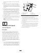
1.1.Loosenthelocknutandunscrewthehighidle
screwafewturns.Whensettingtheenginerpmon
powerunitsconnectedtomodels02710and02711,
replacethehighidlescrewwiththehighidleM5x
50screwsuppliedwith02710and02711(
Figure9).
1
2
3
4
G018377
Figure9
1.Speedcontrollever
3.Locknut
2.Cablescrew
4.Highidlescrew
2.Movethethrottlelever,ontheoperatorcontrol
panel,toobtainthedesiredenginerpm.
3.Turnthehighidlescrewsothattheendofitjust
touchesthespeedcontrollever,andtightenthelock
nut(
Figure9).
4.Checkthehighidlespeedandrepeatthisprocedure
ifnecessary.
5.Loosenthecablescrewandadjustthecablelength
sothatthethrottleleverontheoperatorcontrol
panelissettofullthrottlewhenthespeedcontrol
levertouchesthepreviouslysethighidlescrew .
6.Tightenthecablescrew .
4