
Operator's Manual

g028992
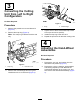
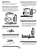
Figure4
1.Bolt5.Nut
2.Alternativeholeposition
6.Springwasher
3.Hand-wheelassembly7.Bearing-adjusterpin
4.Washer
3.Adjustthehand-wheelassemblysothatthe
fasteningcenteriscorrect.
4.Installthehand-wheelassemblyinthe
alternativeholeposition.
5.Installallfastenersandtightensecurely.
6.Repeattheprocedurefortheothercuttingunits
asnecessary.
5
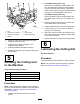
InstallingtheCuttingUnit
totheMachine
Partsneededforthisprocedure:
1Pin
2
Cap-headscrew
2Plainwasher
2
Springwasher
Procedure
Note:Wheninstallingthecuttingunittothemachine,
youmayneedtoadjustthepositionofthehand-wheel
assemblies.Referto4AdjustingtheHand-Wheel
Assemblies(page6).
1.Unlatchandlowertherelevantarmtothe
ground.
2.For200mmcuttingunitsonly:
Removethepinassemblyalreadyttedtothe
arm,anddismantletheM24nut,M24washer,
nutcap,andpear-dropbushing.Installthese
itemsontothe353mmlongpinsuppliedwiththe
cuttingunit.Fitthisassemblyontothearm.
For250mmcuttingunitsonly:
Usingthe400mmlongpinalreadyttedtothe
arm,removethenutcap,nut,andwasherfrom
thepin.
3.Slidethecuttingunitontothepinuntilthearm
bushmateswiththepivotcasting.
4.InstalltheM24washerandlocknutandtighten.
5.Loosenthenutby1/8to1/4turntoallowthe
cuttingunittopivotfreely.
6.Attachthecuttingunitmotortothedriveendof
thecuttingunitusingthefastenersalreadytted
tothemotormounting.
7.Tightentheboltstoatorqueof80N·m(59ft-lb).
6
LubricatingtheCuttingUnit
NoPartsRequired
Procedure
FillallthebearinghousingswithNo.2lithiumgrease.
Note:Thisrequiresasignicantquantityofgrease.
RefertoGreasingtheCuttingUnit(page11).
7