
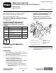
Installation Instructions


6
CompletingtheInstallation
Partsneededforthisprocedure:
2
Spacer
3Plug
Procedure
1.Installthenewspacersontobothfrontpivot
pins,theninstallthecuttingunitsontothe
machineasshown,tightenthelocknut,enabling
thewashertorotateslightly.Installthecenter
cuttingunitwithoutthenewspacerusingthe
sameprocedure(overtighteningwillcausethe
cuttingunitnottopivot);refertoFigure17.
2.Installthereelmotorstothegearboxes.Tighten
thefastenersto80N∙m(59ft-lb);refertoFigure
18.
WARNING
Onmulti-bladedmachines,rotating1reel
cancauseotherbladestorotate,leading
topersonalinjury.
Wrapthebladesorweargloves,anduse
cautionwhenservicingthereelsand
bedknives.
Note:Ifyouneedtorotatethereelbyhand,
replacetheanti-shockvalve(engraved32on
thevalvehead)onthefrontoftheright,left,
andcenterreelmotorswiththeblankingplugs
supplied.Ensurethattheareaiscompletely
cleantopreventanydebrisfromenteringthe
hydraulicsystemwhenchangingtheanti-shock
valvetotheplug.Somelossofhydraulicuidis
tobeexpected.Theanti-shockvalvesneedto
beretainedandinstalledifoperatingwiththe
ailcuttingunits.Torqueto35N∙m(26ft-lb).
3.Greasethegreasettingsandcheckuidlevels.
Note:Donottooverllthegearboxgrease
ttingwithgrease.Stopgreasingwhenthevent
plungerraises.Donotuseanautomaticgrease
gun.
4.Checktoensurethateverythingoperates
correctly.
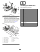
g233627
Figure17
1.Pivotrod
3.Locknut(existing)
2.Spacer4.Cap(existing)
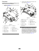
g233617
Figure18
1.Bolt(2),10x40mm4.Locknut(2),10mm
2.Washer(4),10mm
5.Motor
3.Plug(ifrequired)
9