
Operator's Manual


g317791
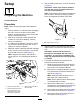
Figure13
1.Nut3.Bolt
2.Largepin
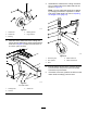
4.Secureeachcylinder-rodendtotheeachlift
armswithasmallpins,bolts(3/8x1-1/4inches),
andnut(3/8inch)asshowninFigure14.
Note:Manuallyrotatetheliftarmtoalignitwith
thecylinder-rodend.
5.Securethesensorbracketpreviouslyremoved
in1PreparingtheMachine(page6)totheright
liftarmusing2carriageboltsand2nuts(3/8
inch)asshowninFigure14.
Note:Ensurethatthesensorbracketdoesnot
interferewiththesensor;referto6Adjustingthe
SensorBracket(page12)ifnecessary.
g300498
Figure14
1.Bolt(3/8x1-1/4inches)4.Carriagebolt
2.Smallpin5.Sensorbracket
3.Nut(3/8inch)
6.Alignthecuttingunitinfrontofthemachine
frameandPTOshaft.
7.InstallthePTOshaftyoketothecuttingunit
gearboxshaftasshowninFigure15.
8.Assembleasocket-headcapscrew(3/8x2-1/4
inches)throughawasher(3/8inch)andthehole
inthedriveshaftyoke(Figure15),andsecure
thecapscrewwithaange-locknut(3/8inch).
9.Assembleasocket-headcapscrew(3/8x2-1/4
inches)throughawasher(3/8inch)andthehole
inthedriveshaftyokefromtheoppositedirection
(Figure15),andsecurethecapscrewwitha
ange-locknut(3/8inch).
10.Incrementallytorquethelocknutsto61N∙m(45
ft-lb)inanalternatingpattern.
Important:EnsurethePTOshaftyoke
boltsaretightenedtothespeciedtorque.
Failuretoproperlytorquetheboltsresultsin
prematurefailureofcriticalparts.
10