
Operator's Manual

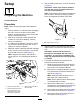


g300498
Figure5
1.Bolt(3/8x1-1/4inches)4.Carriagebolt
2.Smallpin5.Sensorbracket
3.Nut(3/8inch)
g295767
Figure6
Rightsideshown
1.Nut3.Bolt
2.Largepin
g295790
Figure7
1.Liftarm
3.Largepin
2.Machineframe
2
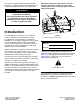
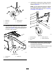
AssemblingtheCaster
ArmsandCasterstothe
CuttingUnit
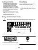
Partsneededforthisprocedure:
2
Castorfork
2
Castorbolt
4Bearing
2Bearingspacer
2Largelocknut
2
Casterarm
12
Carriagebolt(M10)
12
Locknut(M10)
2Tensioningcap
14
HoCspacers
4
Shim
Procedure
1.Assemblethecasterwheelstothecastorfork
asshowninFigure8.
Note:Useonlytheupperaxleshafthole;do
notadjustthepositionofthecasterwheel.
7