
Operator's Manual


g319436
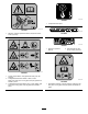
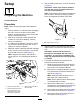
Figure8
1.Castorbolt
4.Bearingspacer
2.Castorfork
5.Largelocknut
3.Bearing
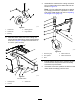
2.Assembleeachcasterarmtothecuttingunit
with6carriagebolts(M10)and6locknuts(M10)
asshowninFigure9;torquethelocknutsto47
to57N∙m(34to42ft-lb).
g314698
Figure9
Leftsideshown
1.Carriagebolt3.Casterarm
2.Locknut
3.Assemblethecasterstothecuttingunitwitha
shimonbothsidesofthecastershafthubas
showninFigure10.
Note:Youcanadjusttheheight-of-cutsetting
bychangingtheamountofspacersoneither
sideofthecastershafthub;refertoAdjusting
theHeightofCut(page13).
g319438
Figure10
1.Tensioningcap
4.Castershafthub
2.HoCspacers5.Casterwheelshaft
3.Shim
4.Ensurethatthedeckislevel;movethedeckto
alevelsurfaceandplacealevelhorizontally
acrossthetopofthedeck.
5.Ifthedeckisnotlevel,positiontheshimsonthe
castershaftaccordinglyuntilitislevel.
8