
Operator's Manual


4
InstallingtheCuttingUnit
totheMachine
Partsneededforthisprocedure:
2
Liftarm
2Largepin
2
Longbolt(3/8x2-3/4inches)
6
Nut(3/8inch)
2
Smallpin
2
Bolt(3/8x1-1/4inches)
2
Carriagebolt(3/8x1-1/4inches)
2
Socket-headcapscrew(3/8x2-1/4inches)
2
Washer(3/8inch)
2
Flange-locknut(3/8inch)
2
Liftarmpin
2Lynchpins
1
Sensorbracket
Procedure
1.Raisethefrontofthemachineandremove
thefronttiresfromthemachine;refertoyour
tractionunitOperator’sManual.
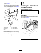
2.Installtheliftarmsandlargepinstothemachine
frame(Figure10).
g317790
Figure10
Rightsideshown
1.Liftarm
3.Largepin
2.Machineframe
3.Securethelargepintotheliftarmusingapair
ofnutsandboltsasshowninFigure11.
g317791
Figure11
1.Nut(3/8inch)3.Longbolt(3/8x2-3/4
inches)
2.Largepin
4.Secureeachcylinder-rodendtotheeachlift
armswithasmallpins,bolts(3/8x1-1/4inches),
andnut(3/8inch)asshowninFigure12.
Note:Manuallyrotatetheliftarmtoalignitwith
thecylinder-rodend.
5.Securethesensorbrackettotherightliftarm
using2carriageboltsand2nuts(3/8inch)as
showninFigure12.
g383542
Figure12
1.Bolt(3/8x1-1/4inches)4.Carriagebolt
2.Smallpin5.Sensorbracket
3.Nut(3/8inch)
10