
Operator's Manual


Setup
1
PreparingtheMachine
NoPartsRequired
Procedure
Note:Retainallremovedpartsunlessotherwise
noted.
1.Parkthemachineonalevelsurface,disengage
thePTO,movetheliftarmstothelowest
position,engagetheparkingbrake,shutoffthe
engine,andremovethekey.
2.Waitforallmovementtostopandallowthe
machinetocoolbeforeadjusting,cleaning,
storing,orrepairingit.
3.Ifacuttingunitisequipped,removethecutting
unitfromthemachineliftarms;refertoyour
cuttingunitOperator’sManual.
4.EnsurethatthePTOdriveshaftisaligned
correctly;refertothePTO-driveshaftalignment
procedureinyourtractionunitOperator’s
Manual.
Important:Ifthemarkingsonthedriveshaft
arenotaligned,severeimbalancemayoccur
inthedrivelinesystem.
5.Iftheliftarmsfortherotarycuttingunitare
installedonthetractionunit,removetheliftarms
asfollows:
A.Raisethefrontofthemachineandremove
thefrontwheelsfromthemachine;referto
yourtractionunitOperator’sManual.
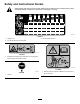
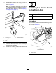
B.Removethe2carriageboltsand2nuts(3/8
inch)thatsecurethesensorbrackettothe
rightliftarm(Figure3).
C.Removethe2bolts(3/8x1-1/4inches),2
nuts(3/8inch),and2smallpinsthatsecure
theliftarmstothecylinders(Figure3).
D.Removethenutandboltssecuringthelarge
pinstotheliftarmsasshowninFigure4.
E.Removetheliftarmsandlargepinsfrom
themachineframe(Figure5).
g300498
Figure3
1.Bolt(3/8x1-1/4inches)4.Carriagebolt
2.Smallpin5.Sensorbracket
3.Nut(3/8inch)
g295767
Figure4
Rightsideshown
1.Nut3.Bolt
2.Largepin
7