
Operator's Manual


g317791
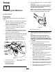
Figure13
1.Nut3.Bolt
2.Largepin
4.Secureeachcylinder-rodendtotheeachlift
armswithasmallpins,bolts(3/8x1-1/4inches),
andnut(3/8inch)asshowninFigure14.
Note:Manuallyrotatetheliftarmtoalignitwith
thecylinder-rodend.
5.Securethesensorbracketpreviouslyremoved
in1PreparingtheMachine(page6)totheright
liftarmusing2carriageboltsand2nuts(3/8
inch)asshowninFigure14.
Note:Ensurethatthesensorbracketdoesnot
interferewiththesensor;referto6Adjustingthe
SensorBracket(page11)ifnecessary.
g300498
Figure14
1.Bolt(3/8x1-1/4inches)4.Carriagebolt
2.Smallpin5.Sensorbracket
3.Nut(3/8inch)
6.Alignthecuttingunitinfrontofthemachine
frameandPTOshaft.
7.InstallthePTOshaftyoketothecuttingunit
gearboxshaftasshowninFigure15.
8.Torquetheboltsto57N∙m(42ft-lb).
Important:ThePTOshaftyokeboltsmust
betightenedtothespeciedtorque.Failure
toproperlytorquetheboltsresultsin
prematurefailureofcriticalparts.
g295791
Figure15
1.Nut2.Bolt
9.Securetheailtotheliftarmsusingtheliftarm
pinsandlynchpins(Figure29).
10