
Installation Instructions


g342986
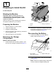
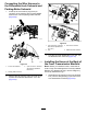
Figure24
1.Frontofthemachine3.Straighttting
(port-FAL—front
transmissionmanifold)
2.Lefttraction-motorhose
(markedFAL)
2.Torquetheswivelnutofthe90°returnhose
ttingto45N∙m(34ft-lb).
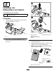
3.Assemblethehydraulic-returnhose(marked
DC)ontothestraightttinginport-DCofthe
fronttransmissionmanifold(Figure25).
g343020
Figure25
1.Frontofthemachine
3.Hydraulic-returnhose
(markedDC)
2.Straighttting
(port-DC—front
transmissionmanifold)
4.Torquetheswivelnutofthe90°returnhose
ttingto16.5N∙m(13ft-lb).
5.Assemblethe90°ttingontothestraighttting
atport-Aofthefronttransmissionmanifold
(Figure26).
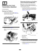
g343023
Figure26
1.Hydraulic-pumphose
(markedA)
3.Straighttting(port-A)
2.90°tting4.Frontofthemachine
6.Torquethe90°ttingto160N∙m(118ft-lb).
7.Assemblethehydraulic-pumphose(markedA)
ontothe90°tting(Figure26).
8.Torquetheswivelnutofthe90°pumphose
ttingto74.5N∙m(55ft-lb).
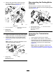
InstallingtheHosesattheFrontof
theFrontTransmissionManifold
1.Assembletherighttraction-motorhose(marked
FAR)ontothestraightttinginport-FARofthe
fronttransmissionmanifold(Figure27).
g343019
Figure27
1.Straighttting
(port-FAR—front
transmissionmanifold)
3.Frontofthemachine
2.Righttraction-motorhose
(markedFAR)
10