
Installation Instructions


2
Installingthe
Differential-LockSwitch
Partsneededforthisprocedure:
1
Differential-lockswitch
Procedure
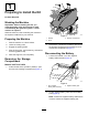
1.Removetheplugfromthepanelofthecontrol
consoleasshowninFigure3.
g342638
Figure3
1.Plug
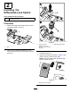
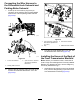
2.Liftthe8-pinconnectorlabeledDIFFLOCK
SWITCHthroughtheholeinthecontrolconsole
(Figure4).
g342637
Figure4
1.8-pinconnector
(labeledDIFFLOCK
SWITCH—controlconsole
harness)
2.Differential-lockswitch
3.Plugthedifferential-lockswitchintothe8-pin
connector(Figure4).
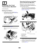
4.AlignthelockswitchasshowninFigure5and
insertitintothecontrol-consolehole.
Note:Ensurethattheswitchsnapssecurely
intothecontrolconsole.
g342636
Figure5
1.Rightsideofthemachine
3