
Installation Instructions


g342837
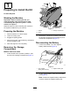
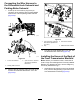
Figure10
1.Frontofthemachine3.90°tting
2.Hydraulic-pumphose
(markA)
4.Straighttting(port-A)
4.Plugthehydraulic-pumphose,applyapieceof
tapetothehose,andwriteAonthetape.
5.Removethe90°ttingfromthestraightttingat
port-Aofthefronttransmissionmanifold(Figure
10).
Note:Retainthe90°ttingforinstallationofthe
newfronttransmissionmanifold.
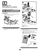
6.Removethehydraulic-returnhosefromthe
straightttinginport-DCofthefronttransmission
manifold(Figure11).
g342838
Figure11
1.Straighttting
(port-DC—front
transmissionmanifold)
3.Frontofthemachine
2.Hydraulic-returnhose
(markDC)
7.Plugthehydraulic-returnhose,applyapieceof
tapetothehose,andwriteDConthetape.
RemovingtheHosesattheFront
oftheTransmissionManifold
Note:Makeanoterecordingthepositionand
orientationofallhoses,ttings,andelectrical
connectorsthatyoudisconnectorremovefromthe
fronttransmissionmanifold.
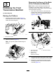
1.Removetheleftandrightbrake-pressure
hosesfromtheT-ttingatport-PBofthefront
transmissionmanifold(Figure12).
g342840
Figure12
1.Frontofthemachine3.T-tting(port-PB)
2.Rightbrake-pressurehose
or(markrightPB)
4.Leftbrake-pressurehose
(markleftPB)
2.Plugtheleftandrightbrake-pressurehoses,
applyapieceoftapetoeachhose,andwriteleft
PBorrightPBonthetape.
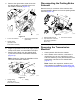
3.Removethechargepressure-supplyhosefrom
thestraightttinginport-CPttingofthefront
transmissionmanifold(Figure13).
g342839
Figure13
1.Chargepressure-supply
hose(markCP)
3.Frontofthemachine
2.Straighttting
(port-CP—front
transmissionmanifold)
4.Plugthechargepressure-supplyhose,applya
pieceoftapetothehose,andwriteCPonthe
tape.
5