
Installation Instructions

1
InstallingtheElectricControl
Box
Partsneededforthisprocedure:
1
Control-boxbracket
2
Setscrew(8x25mm)
10
Washer(8mm)
5
Locknut(8mm)
1Electriccontrolbox
4
Self-tappingscrews(6x12mm)
1Umbilicalcableassembly
1
Liftmanifold
1
Solenoidvalve(closed)
1
Solenoid
4
Bondedseal(1/4inch)
3
Adapter(1/4inchmalex1/4inchmale)
1
Plug(1/4inchmale)
2
Plug(3/8inchmale)
5
Bondedseal(3/8inch)
3
Adapter(3/8inchmalex3/8inchmale)
1
Adapter(1/4inchmalex3/8inchmale)
1
Checkvalve(3/8inch)
1
Coupling(3/8inchmalex3/8inchfemale)
1
Elbow(3/8inchmalex3/8inchfemale)
1
Tee(3/8inchmalex3/8inchfemalex3/8inchmale)
1
Crosstting(1/4inchmale)
1
Elbow(1/4inchfemalex1/4inchfemale)
2
Bolt(8x75mm)
1
Bolt(8x65mm)
1
Hose(3/8inchx575mm)
1
Hose(1/4inchx2.16m)
Procedure
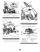
1.Parkthemachineonalevelsurface,disengagethe
tractorPTO,andengagetheparkingbrakeofthe
tractorandtheparkingbrakeofthetrailedmower.
2.Lowerthecuttingunitstotheground.
3.Turnoffthetractorengineandremovetheignitionkey.
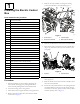
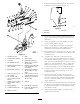
4.Removeallcontrolcablesfromtheliftandoverride
controlvalvesFigure1.
5.Removethenutsandboltssecuringtheexisting
control-leverbrackettothemachine(Figure1).
g028993
Figure1
1.Controllevers3.Controlcables
2.Control-leverbracket4.Bolts(nutsnotshown)
6.Removeanddiscardthecontrolleversandthebracket.
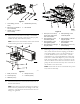
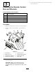
7.Disconnectallhoseconnectionstotheoverridevalve
(Figure2),andremovethehosethatconnectstothe
rearpump.
g025355
Figure2
1.Liftvalve2.Overridevalve
8.Disconnectallhoseconnectionstotheliftcontrol
valve(Figure2).
9.Removetheliftcontrolvalveandtheoverridecontrol
valvefromthemachine.
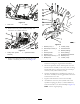
10.Fastenthecontrol-boxbrackettotheexistinglift-valve
mountingbracketonthefrontofthechassisusing2
setscrews(8x25mm),4plainwashers(8mm),and2
locknuts(8mm);refertoFigure3.
4