
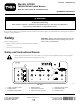
Installation Instructions

g025356
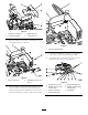
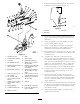
Figure3
1.Setscrew(8x25mm),23.Washer(8mm),4
2.Control-boxbracket4.Locknut(8mm),2
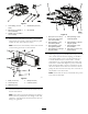
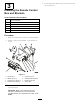
11.Fastentheelectriccontrolboxtothebracketusing4
self-tappingscrews(6x12mm).
g025357
Figure4
1.Electriccontrolbox
2.Self-tappingscrew(6x12
mm),4
12.Taketheumbilicalcableassemblyandidentifytheend
with2controlboxconnectors.Passthisendofthe
cablethroughthekeyhole-shapedholeatthefrontof
thebracketandsecureitwiththebacknutsprovided.
g025358
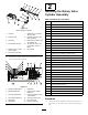
Figure5
1.Umbilicalcableassembly
13.Connectthe2umbilicalcableplugstotheelectric
controlbox,usingthelargecabletieprovided.
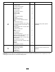
14.Assemblethelift-controlblockassemblywiththe
ttingsasshowninFigure6andFigure7.
6
5
7
1
2
45 45 31
G025630
g025630
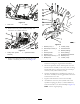
Figure6
1.Bondedseal(1/4inch)5.Bondedseal(3/8inch)
2.Adapter(1/4inchmalex
1/4inchmale)
6.Adapter(3/8inchmalex
3/8inchmale)
3.Plug(1/4inchmale)7.Liftmanifold
4.Plug(3/8inchmale)
5