
Installation Instructions

1
G025513
2345
g025513
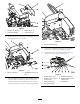
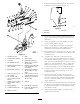
Figure7
1.Crosstting(1/4inch
male)
4.Bondedseal(1/4inch)
2.Elbow(1/4inchfemalex
1/4inchfemale)
5.Liftmanifold
3.Adapter(1/4inchmalex
1/4inchmale)
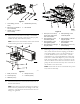
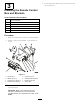
15.Fastenthelift-controlblockassemblytothebracket
using2bolts(8x75mm),1bolt(8x65mm),6plain
washers(8mm),and3locknuts(8mm).
Note:Someofthesolenoidsmayneedtobeloosened
orremovedtogainaccesstotheboltholes.
1
G025408
3
3
5
2
4
3
3
g025408
Figure8
1.Bolts(8x75mm)4.Bolt(8x65mm)
2.Locknut(8mm)5.Locknuts(8mm)
3.Washers(8mm)
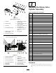
16.Connectthelifthosestotheirrelevantconnectorson
theliftcontrolblock.
Note:Somehoseswillrequirearrangingforneatness.
Wherenecessary,slackenthehosettingsateachend,
orientatetosuitandensurethatbothendsofthehose
ttingsaretightened.
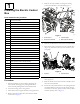
1
7
G025409
2 3
8 6 5 4
g025409
Figure9
1.Hose(1/4inchx2.16m),
totherotaryvalveatthe
rearofthemachine
5.Hose(existing),tothe
centerliftcylinder
2.Hose(existing),tothe
frontleftliftcylinder
6.Hose(existing),totheleft
wingliftcylinder
3.Hose(existing),tothe
frontrightliftcylinder
7.Hose(existing),tothe
frontmanifold
4.Hose(existing),totheright
wingliftcylinder
8.Hose(3/8inchx57.5cm),
totheliftpump
17.ReferringtoFigure10,assemblealinebody,asolenoid
valve,andasolenoid.Fitthecoupling,thebonded
seal,andtheelbowtoport1ofthelinebody.Fita
3/8inchbondedseal,a3/8inchmalex3/8inch
maleadapter,two3/8inchbondedseals,checkvalve,
and3/8x1/4inchmaleadaptertoport2oftheline
body.FittheassemblytotheteeonthePportofthe
liftcontrolblock.Fitthehosefromtheteetothelift
pump.Fitthehosefromtherotaryvalveattherearof
themachinetothecheckvalve.
Note:Ensurethatthearrowonthecheckvalvepoints
awayfromthelinebody.
6