
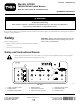
Installation Instructions

g188311
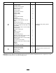
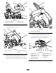
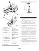
Figure10
Somettingsnotshown
1.Solenoid7.Adapter(1/4inchmalex
3/8inchmale)
2.Solenoidvalve8.Coupling(3/8inchmalex
3/8inchfemale)
3.Linebody
9.Elbow(3/8inchmalex3/8
inchfemale),90°
4.Bondedseal(3/8inch)10.Tee(3/8inchmalex3/8
inchfemalex3/8inch
male)
5.Adapter(3/8inchmalex
3/8inchmale)
11.Liftmanifold
6.Checkvalve(3/8inch)
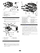
18.Connecttheelectricalleadsfromtheelectriccontrol
boxtotherelevantsolenoids.
1
2
3
4
5
6
7
5
1
6
2
7
3
8
4
8
9
10
G025362
1112
g025362
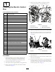
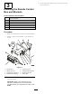
Figure11
1.Rightwing(labeled2C)
7.Labeled2F
2.Middle(labeled2B)8.Cutterreverserotation
(labeled1)
3.Leftwing(labeled2A)
9.Tothesolenoidattherear
ofthemachine
4.Liftoverride(labeled3)
10.Totheproximitysensor
5.Labeled2D
11.Liftcontrolblock
6.Labeled2E12.Electriccontrolbox
2
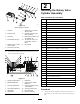
InstallingtheRotaryValve
CylinderAssembly
Partsneededforthisprocedure:
1Actuatorbracket
1Proximitysensor
1Proximity-sensorbracket
2
Setscrew(6x25mm)
4
Washer(6mm)
2
Locknut(6mm)
2
Capscrew(5x20mm)
4
Washer(5mm)
2
Locknut(5mm)
1
Spacer
1
Solenoidvalve(closed)
1Linebody
2
Bondedseal(3/8inch)
1
Adapter(1/4inchfemalex3/8inchmale)
1
Bondedseal(1/4inch)
1
Hose(1/4inchx380mm),90°xstraight
1
Tee(1/4inchmalex1/4inchmalex1/4inchfemale)
1
Adapter(1/4inchmalex1/4inchmale),1.4mmorice
1
Cylinderrodspringpin
1Bush
1
Washer(10mm)
1Valvecylinder
1
Bondedseal(3/4inch)
1
Adapter(1/4inchmalex3/4inchmale)
1
Swiveltee(1/4inchfemale)
1
Adapter(1/4inchmalex1/4inchmale),0.8mmorice
1
Hose(1/4inchx2.156m)
1
Adapter(1/4inchmalex3/8inchmale)
1
Splitpin
8
Cabletie
1
Hosetie(368x4.8mm)
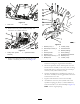
Procedure
1.Attherearofthemachine,removetherearcoverto
gainaccesstotherotaryvalvecontrolsystem(Figure
12).
7