
Installation Instructions

1
G025360
2
g025360
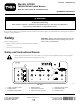
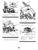
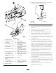
Figure12
1.Rearcover2.Bolts
2.Removetherotaryvalvecylinderassemblyand
disconnectthecylinderfeedhose.
1
G025361
2
g025361
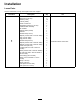
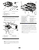
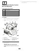
Figure13
1.Rotaryvalvecylinder
assembly
2.Cylinderfeedhose
3.Removetheappropriatescrewsecuringtherotary
brackettotherotaryvalveasshowninFigure14.
1
9
13
12
11
14
2 3
4
5
6
1
8
G025363
7
10
g025363
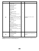
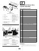
Figure14
1.Washer(6mm),48.Locknut(6mm)
2.Setscrew(6x25mm),2
9.Actuatorbracket
3.Spacer10.Washer(existing)
4.Proximitysensor
11.Screw(existing)
5.Washer(5mm)
12.Proximity-sensorbracket
6.Capscrew(5x20mm),213.Washer(5mm)
7.Backlaplever
14.Locknut(5mm)
4.Assembletheactuatorbracketontotherotarybracket,
andsecureitusingtheoriginalscrewandwasher.
5.Mounttheproximitysensorandthespacerontothe
bracket.Fitthisassemblytotherotaryvalvemounting
bracketandsecureitwith2setscrews(6x25mm),4
washers(6mm)and2locknuts(6mm).
6.Operatethebacklapleverandadjustthepositionof
thesensorassemblysothatthegapbetweenthesensor
andtheactuatoris5mm.
7.Tightenallthefastenersonthesensorassembly.
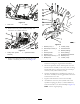
8.Assemblethenewrotaryvalvecylinderwithanew
cylinderrodspringpin,bush,3/4inchbondedseal,
and3/4inchmalex1/4inchmaleadapter(Figure15).
Note:Usetheoriginalsprings.
8