
Installation Instructions
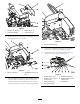

1
2
3
4
5
19
21
4
20
18
17
16
15
6
7
12
10
11
8
9
7
10
14
13
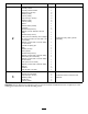
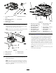
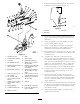
G025354
g025354
Figure15
1.Solenoid(12volt)
13.Bush
2.Solenoidvalve(closed)
14.Valvecylinder
3.Linebody
15.Bondedseal(3/4inch)
4.Bondedseal(3/8inch)16.Adapter(1/4inchmalex
3/4inchmale)
5.Adapter(1/4inchfemalex
3/8inchmale)
17.Swiveltee(1/4inchfemale
x1/4inchfemalex1/4
inchfemale)
6.Bondedseal(1/4inch)18.Adapter(1/4inchmalex
1/4inchmale),0.8mm
orice
7.Hose(1/4inchx38cm),
90°xstraight
19.Hose(1/4inchx2.156m),
tothefrontsolenoidvalve
8.Tee(1/4inchmalex
1/4inchmalex1/4inch
female)
20.Adapter(1/4inchmalex
3/8inchmale)
9.Adapter(1/4inchmalex
1/4inchmale),1.4mm
orice
21.Splitpin
10.Spring(existing)22.Cableties(8),notshown
11.Cylinderrodspringpin23.Largehosetie(368x4.8
mm),notshown
12.Washer(10mm)
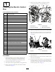
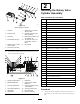
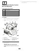
9.Removethebacklapreleaseleverfromtherearhole,
andinstallitintothefronthole(Figure16).
1
2
3
G025364
g025364
Figure16
1.Frontslot3.Fronthole
2.Rearhole
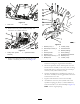
10.Fittherotaryvalvecylinderassemblyinthefrontslot
(Figure16),andsecureitusingtheoriginalboltand
slidebush.
11.Attachthecylindertotherotarybracketusingthe
washer(10mm)andthesplitpin.
12.Fitthe1/4inchfemaleteeandthe1/4inchmale
adapter(0.8mmorice)tothecylinderport,and
connectthehosefromthefrontsolenoidvalve.
13.Disconnectthehoseonthelower1/4inchportofthe
rearmanifold.Fita1/4inchmaleteetotheport,and
connectthehose.
14.Assemblealinebodywithasolenoidvalveand
solenoid.Fita3/8inchbondedsealanda3/8inchx
1/4inchmaleadapter(existing),toport1oftheline
body.Fita3/8inchbondedseal,a3/8inchx1/4inch
adapter,a1/4inchbondedseal,anda1/4inchmale
adapter(1.4mmorice)toport1ofthelinebody.
Connecttheassemblytothevalvecylinderlinebody.
15.Connectthehosetotheteeontherearmanifold.
Connecttheotherendtothettingsonthevalve
cylinderlinebody.
16.Runthecablesfromthecontrolboxtotherear
solenoidvalveandtheproximityswitchbracketalong
thecenterofthemachine(underthehydraulictank)to
therear.Connectthecablestothesolenoidandthe
switch,respectively.
17.Keeptherearsolenoidcableandtherearcylinderhose
tidybyusingthe8cabletiesandthelargehosetie(368
x4.8mm)tosecurethemtotheexistinghosesunder
thehydraulicoiltank.
18.Checkallthefastenersandhoseconnections,and
tightenthemasnecessary.
9